A transmission assembly device with magneto-rheological clutch, braking, and variable speed control
What is AI technical title?
AI technical title is built by Patsnap AI team. It summarizes the technical point description of the patent document.
A magnetorheological and clutch technology, applied in the direction of fluid transmission, transmission, fluid clutch, etc., can solve the problems of optimal combination of difficult-to-separate devices, low degree of automation control, and various types of parts, so as to control social production costs. , Solve the effect of automation function and simple structure
Active Publication Date: 2015-10-14
山东格新精工有限公司
View PDF6 Cites 0 Cited by
Summary
Abstract
Description
Claims
Application Information
AI Technical Summary
This helps you quickly interpret patents by identifying the three key elements:
Problems solved by technology
Method used
Benefits of technology
Problems solved by technology
[0004] The traditional power transmission, load drive and mechanism control basically adopt the form of separate installation to configure the relevant mechanical devices. The design distribution of the clutch, brake and speed change transmission devices required for the transmission process is relatively scattered, and the types of parts involved are very complicated. , the degree of automatic control of the device is very low. Therefore, compared with the present invention, the structural parts of the traditional product are large in size, the number of parts is large, and the production cost is high. Moreover, it is difficult for the traditional design technology to perform the functions of the sorting device. Optimize the combination, it is more difficult to support the technical upgrade of the mechatronics of the product
At present, no precedent has been found to integrate the above-mentioned sorting device into a power transmission assembly device and apply magnetorheological control technology to control and manage the power transmission function process
Method used
Image
Click on the blue label to locate the original text in one second.
Reading with bidirectional positioning of images and text.
Examples
Embodiment
[0034] The invention innovatively integrates the three functional mechanisms of the clutch, brake and transmission into a drive box assembly component unit, and takes the lead in applying magnetorheological technology to the field of power control of small and medium-sized vehicles, and solves the problem of using magnetorheological fluid As a power transmission medium, it realizes the operation, control and management of the clutch, brake and speed change of the vehicle power.
[0035] 1. Process procedure
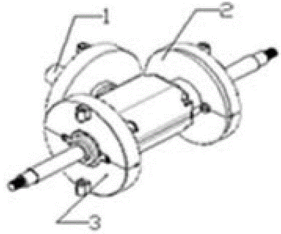
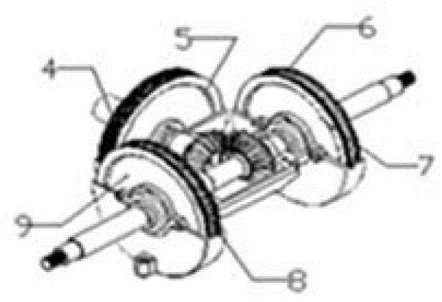
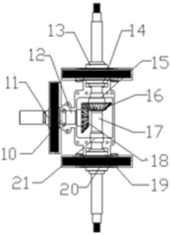
[0036] 1. First prepare the parts and magnetorheological fluid materials produced according to the attached drawings.
[0037]Specifically, it includes a shaft coupling 1, an upper housing 2, a lower housing 3, a clutch coil 4, a clutch housing 5, a brake coil, a brake housing, a clutch frame shaft 10, a clutch disc shaft 11, a clutch bearing 12, Brake disc frame, reversing bearing, reversing gear 16, reversing shaft 17 and power gear 18, described shaft coupling 1, clut...
PUM
Abstract
The invention belongs to the technical field of drive assembly devices, in particular to a magneto-rheological clutch, brake and variable speed control drive assembly device, which is formed by assembling a coupling, an upper shell, a lower shell, a clutch coil, a clutch shell, a brake coil, a brake shell, a clutch holder shaft, a clutch disc shaft, a clutch bearing, a brake pad bracket, a reversing bearing, a reversing gear, a reversing shaft and a power gear; when a vehicle starts, the coupling inputs power to the clutch disc shaft; when the vehicle runs, current is input into the clutch coil, a magneto-rheological material is subjected to phase change, and the power is transmitted to the reversing shaft from the clutch disc shaft through the power gear and the reversing gear; and when the vehicle is braked, the current input into the clutch coil and the brake coil is cut off, the magneto-rheological material is subjected to phase change, and the brake pad bracket and the reversing shaft are in a brake locking state. The device solves technical problems to achieve light-weight product, simple structure, material reduction and intelligent control, and powerful support is provided for promoting new materials, new technologies, new processes and technical upgrade of products.
Description
[technical field] [0001] The invention relates to the technical field of transmission assembly devices, in particular to a transmission assembly device controlled by a magneto-rheological clutch, a brake, and a transmission, and a transmission method and application thereof, which are suitable for small and medium-sized electric vehicles, engineering logistics vehicles, and agricultural vehicles , Lifting and handling vehicles, marine driving devices, mechanical power devices and other necessary supporting ranges of use. [Background technique] [0002] Magneto-rheological fluid is a new type of phase-change material. It is a magnetic particle suspension mixed with high magnetic permeability and low hysteresis (micron or even nanoscale) soft magnetic particles and non-magnetic liquid. When there is no magnetic field, the suspended particulate iron particles move freely with the liquid; when a magnetic field is applied, these suspended particulate iron particles are attracted ...
Claims
Application Information
Patent Timeline
Application Date:The date an application was filed.
Publication Date:The date a patent or application was officially published.
First Publication Date:The earliest publication date of a patent with the same application number.
Issue Date:Publication date of the patent grant document.
PCT Entry Date:The Entry date of PCT National Phase.
Estimated Expiry Date:The statutory expiry date of a patent right according to the Patent Law, and it is the longest term of protection that the patent right can achieve without the termination of the patent right due to other reasons(Term extension factor has been taken into account ).
Invalid Date:Actual expiry date is based on effective date or publication date of legal transaction data of invalid patent.

