
Fused salt heat storage and heat release peak load regulating system for thermal power generating unit

A thermal power unit, molten salt technology, applied in mechanical equipment, steam engine installations, machines/engines, etc., can solve the problems of long response time, limited range, limited water storage capacity of deaerators and condensers, etc. The effect of reducing the amount of steam used and increasing the amount of steam

Pending Publication Date: 2018-07-24
XIAN THERMAL POWER RES INST CO LTD +1
View PDF0 Cites 12 Cited by
  • Summary
  • Abstract
  • Description
  • Claims
  • Application Information

AI Technical Summary

Problems solved by technology

The power grid constantly requires units to respond quickly to load changes, and the current operation and control methods of thermal power units have been difficult to meet the demand
[0004] In order to improve the peak shaving capability of thermal power units, in recent years there has been a technology that uses the water storage potential of the hot well of the deaerator and condenser to change the condensate amount in a short time to change the instantaneous power of the unit, but it is limited by the deaerator and condenser Water storage capacity, there are problems such as not wide range, long response time, etc.

Method used


Image

  • Fused salt heat storage and heat release peak load regulating system for thermal power generating unit

Examples


Embodiment Construction

[0033]The present invention is described in further detail below in conjunction with accompanying drawing:

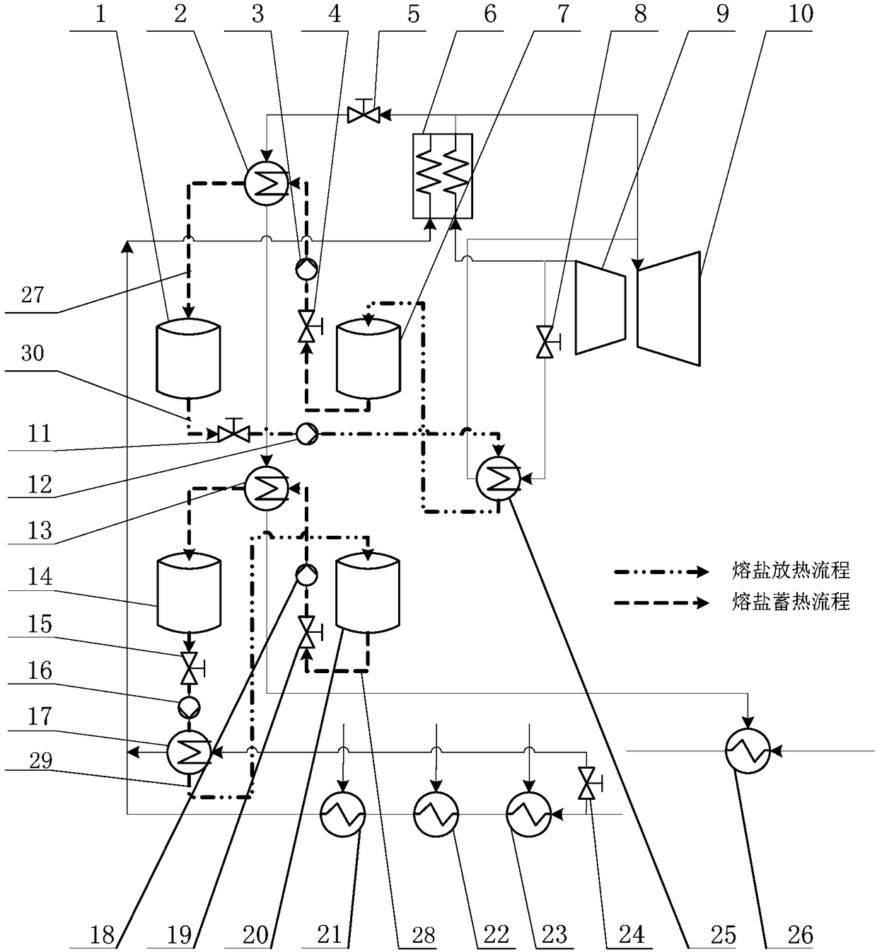
[0034] see figure 1 , the present invention includes a boiler 6, a high-pressure cylinder 9, a medium-pressure cylinder 10, a molten salt heat storage system, a grade I molten salt low-temperature exothermic system and a II-grade molten salt high-temperature exothermic system, a high-pressure heater and a low-pressure condensate heater 26 , wherein the molten salt thermal storage system includes a Class I molten salt high temperature thermal storage system and a II molten salt low temperature thermal storage system, and the high pressure heaters include No. 1 high pressure heater 21, No. 2 high pressure heater 22 and No. 3 high pressure heater 23 ;Class I molten salt high temperature heat storage system includes high temperature molten salt hot tank 1, heat storage high temperature molten salt heat exchanger 2, heat storage high temperature molten salt pump 3, heat stor...


PUM

PropertyMeasurementUnit
Boiling pointaaaaaaaaaa

Abstract

The invention discloses a fused salt heat storage and heat release peak load regulating system for a thermal power generating unit. According to the fused salt heat storage and heat release peak loadregulating system, a fused salt heat storage system, an I-stage fused salt low-temperature heat release system and a II-stage fused salt high-temperature heat release system are additionally arrangedon the basis of the original thermal power generating unit, and therefore peak load regulating of a power grid is realized through heat storage and heat release of fused salt; when the dispatching load of the power grid is decreased, part of high-temperature reheat steam is extracted from an outlet of a boiler reheater and exchanges heat with the fused salt in the fused salt heat storage system, and therefore consumption and utilization of the reheat steam in the electricity utilization off-peak season are completed; when the dispatching load of the power grid is increased, a part of high-pressure feedwater flowing to a high-pressure heater is divided into the I-stage fused salt low-temperature heat release system to exchange heat with the fused salt; and meanwhile, the steam discharge amount of a high-pressure cylinder is increased, part of increased exhaust steam of the high-pressure cylinder is fed into the II-stage fused salt high-temperature heat release system to exchange heat with the high-temperature fused salt, the heated steam enters an intermediate-pressure cylinder to apply work, the amount of the steam entering the intermediate-pressure cylinder and the output of a steam turbine can be increased, and the electric power of the thermal power generating unit can be rapidly increased.

Description

【Technical field】 [0001] The invention belongs to the technical field of thermal power generation, and in particular relates to a thermal power unit molten salt heat storage and release heat peak regulation system. 【Background technique】 [0002] Thermal power generation is an important part of the power structure, and it will still occupy a dominant position at present and for a long period of time in the future. With the slowdown in the growth of electricity demand in the whole society and the large-scale development of renewable energy, it is the general trend to improve the flexibility of thermal power operation, which will play an important role in the large-scale consumption of new energy. Therefore, the long-term operation of thermal power units with low load, and as a means of peak regulation, to better absorb new energy power generation will be the main direction of future development of thermal power units. [0003] With the rapid increase in the proportion of new...

Claims


Application Information

Patent Timeline
IPC IPC(8): F01K13/02F01K17/02F01K21/00
CPCF01K13/02F01K17/02F01K21/00
Inventor 范庆伟谢天黄嘉驷常东锋王伟雒青付亦葳张建元
Owner XIAN THERMAL POWER RES INST CO LTD
Learn More