Biological sludge heating and thermal hydrolysis system and process

A technology of biological sludge and thermal hydrolysis, applied in water/sludge/sewage treatment, sludge treatment, sludge treatment through temperature control, etc., can solve the problem of increasing the amount of sludge treatment and processing energy consumption, heating needs Long time, large steam consumption and other problems, to achieve the effect of improving mixing efficiency and heat transfer efficiency, reducing heating time and steam consumption, and enhancing heat transfer effect

Active Publication Date: 2021-12-31
CHANGSHA UNIVERSITY OF SCIENCE AND TECHNOLOGY +1
View PDF4 Cites 0 Cited by
  • Summary
  • Abstract
  • Description
  • Claims
  • Application Information

AI Technical Summary

Problems solved by technology

However, the intermittent thermal hydrolysis system and technology still have the following disadvantages: in the large-volume preheating slurry tank, the steam is preheated, and the dry solid concentration of the dewatered sludge is as high as 16-18%. Mud has poor heating uniformity and low heat transfer efficiency, resulting in long heating time and large steam consumption; the thermal hydrolysis process of CAMBI products requires multiple thermal hydrolysis reactors to achieve continuous operation, and the process control is complicated , high cost of equipment investment, etc.
The continuous vertical baffle thermal hydrolysis system represented by Veolia's Exelys products mainly installs baffles in the vertical thermal hydrolysis reactor and realizes the sludge in the thermal hydrolysis reactor through the steam lifting effect. Internal circulation flow to achieve the required reaction time (about 20min). Due to the poor fluidity and mixing properties of high solid content sludge, this technology has low heat transfer efficiency and high heating efficiency when dealing with high solid content sludge. Poor uniformity, high steam consumption, poor continuous operation stability
If the concentration of sludge solids is reduced, the sludge treatment volume and treatment energy consumption will be significantly increased, resulting in higher treatment costs
Thermal oil pipe heating systems (such as Ovivo water LysoTherm products) use oil heat pipe heaters to heat sludge, which will also result in low heat transfer efficiency due to the high viscosity and poor fluidity of sludge with high solid content, thus increasing equipment manufacturing and operating costs
It can be seen that the equipment used in the existing high-temperature thermal hydrolysis technology generally has the following problems when dealing with sludge with high solid content: poor heat transfer effect, uneven heating of materials, large amount of steam consumption, long heating time, stable continuous operation Poor performance, which leads to problems such as high equipment investment cost, high processing cost, and poor processing effect
In addition, in the actual application process, the existing high-temperature thermal hydrolysis equipment and technology are used to pretreat biological sludge such as activated sludge, and then the products after high-temperature thermal hydrolysis treatment are subjected to anaerobic digestion, which cannot significantly improve the overall production capacity. This is mainly because the existing thermal hydrolysis equipment and process are difficult to hydrolyze refractory organic matter in biological sludge such as activated sludge, and these refractory organic matter are difficult to effectively degrade in the existing anaerobic digestion process, resulting in anaerobic digestion The rate is reduced, making the degradation effect of anaerobic digestion and the overall gas production poor
The existence of the above problems limits the application effect and application scope of anaerobic digestion technology, which is very unfavorable for the effective treatment and resource reuse of biological sludge, and cannot bring out the due value of biological sludge

Method used


Image

  • Biological sludge heating and thermal hydrolysis system and process
  • Biological sludge heating and thermal hydrolysis system and process
  • Biological sludge heating and thermal hydrolysis system and process

Examples


Embodiment 1

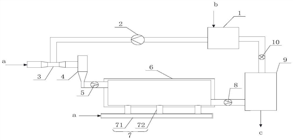
[0044] A biological sludge heating and thermal hydrolysis system, such as figure 1 As shown, it includes material preheater 1, material delivery pump 2, primary steam ejector 3, material storage 4, feed pump 5, thermal hydrolysis reactor 6, discharge pump 8, A steam flasher 9 and a pressure relief valve 10, as well as a secondary steam ejector 7 for heating the biological sludge in the thermal hydrolysis reactor 6.

[0045] In this embodiment, the secondary steam ejector 7 includes an external steam delivery pipe 71 and at least one external steam injection pipe 72. One end of the external steam injection pipe 72 communicates with the external steam delivery pipe 71, and the other end communicates with the external steam delivery pipe 71. The hydrolysis reactor 6 communicates.

[0046] In this embodiment, the thermal hydrolysis reactor 6 is a cylindrical structure arranged horizontally, and the biological sludge enters the thermal hydrolysis reactor 6 from the material inlet ...

Embodiment 2

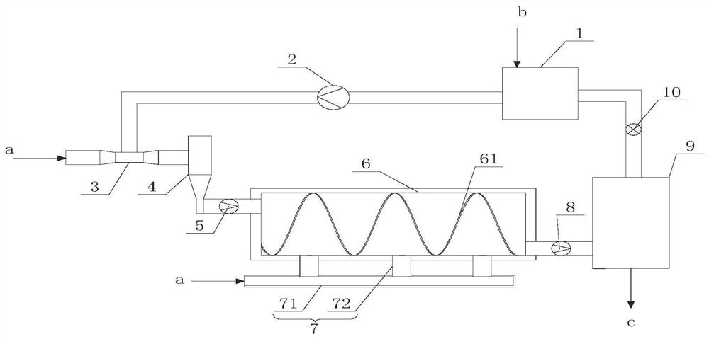
[0052] A biological sludge heating and thermal hydrolysis system, such as figure 2 and 3As shown, it includes material preheater 1, material delivery pump 2, primary steam ejector 3, material storage 4, feed pump 5, thermal hydrolysis reactor 6, discharge pump 8, A steam flasher 9 and a pressure relief valve 10, as well as a secondary steam ejector 7 for heating the biological sludge in the thermal hydrolysis reactor 6.

[0053] In this embodiment, the secondary steam ejector 7 includes an external steam delivery pipe 71 and at least one external steam injection pipe 72. One end of the external steam injection pipe 72 communicates with the external steam delivery pipe 71, and the other end communicates with the external steam delivery pipe 71. The hydrolysis reactor 6 communicates.

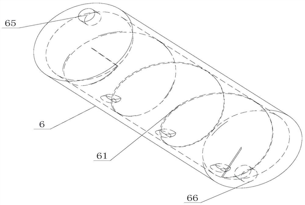
[0054] In this embodiment, the thermal hydrolysis reactor 6 is a cylindrical structure arranged horizontally, and a spiral deflector 61 is arranged inside the thermal hydrolysis reactor 6 . In...

Embodiment 3

[0059] A biological sludge heating and thermal hydrolysis system, such as Figure 4 and 5 As shown, it includes material preheater 1, material delivery pump 2, primary steam ejector 3, material storage 4, feed pump 5, thermal hydrolysis reactor 6, discharge pump 8, A steam flasher 9 and a pressure relief valve 10, as well as a secondary steam ejector 7 for heating the biological sludge in the thermal hydrolysis reactor 6.

[0060] In this embodiment, the secondary steam ejector 7 includes an external steam delivery pipe 71 and at least one external steam injection pipe 72. One end of the external steam injection pipe 72 communicates with the external steam delivery pipe 71, and the other end communicates with the external steam delivery pipe 71. The hydrolysis reactor 6 communicates.

[0061] In this embodiment, the thermal hydrolysis reactor 6 is a cylindrical structure arranged horizontally, and the thermal hydrolysis reactor 6 is provided with an inclined guide plate 62 ....


PUM


Abstract

The invention discloses a biological sludge heating and thermal hydrolysis system and process. The system includes a material preheater, a material delivery pump, a primary steam injector, a material storage device, a feed pump, Thermal hydrolysis reactor, discharge pump, steam flasher and pressure relief valve, and secondary steam ejector for heating the biological sludge in the thermal hydrolysis reactor. The process uses the system described above for heating and thermal hydrolysis. The biological sludge heating and thermal hydrolysis system of the present invention has the advantages of good heat transfer effect, good material heating uniformity, small steam consumption, short heating time, good continuous operation stability, etc., and can be widely used to degrade biological sludge, and has the advantages of Very good application value and application prospect. The biological sludge heating and thermal hydrolysis system process of the present invention has the advantages of simple process, convenient operation, low treatment cost, high treatment efficiency, good treatment effect, etc., which is conducive to improving the utilization rate of biological sludge and expanding the application range of anaerobic digestion .

Description

technical field [0001] The invention belongs to the field of biological sludge resource treatment, and relates to a biological sludge heating and thermal hydrolysis system and process. Background technique [0002] With the continuous development of society and economy, the output of biological sludge such as biogas residue and activated sludge is increasing. At present, the research hotspots of biological sludge pretreatment include high-temperature thermal hydrolysis, biological acidification hydrolysis, high-temperature and high-pressure oxidation, ultrasonic treatment, high-temperature homogenization, and ozone chemical treatment. Temperature to 150-180°C to achieve the purpose of destroying the floc structure, destroying the cell wall tissue and degrading some macromolecular substances. Since high-temperature thermal hydrolysis can degrade refractory solid particles and macromolecular substances in biological sludge, thereby increasing the content of organic acids and ...

Claims


Application Information

Patent Timeline
Patent Type & Authority Patents(China)
IPC IPC(8): C02F11/18C02F11/00
CPCC02F11/00C02F11/18
Inventor 赵李铁昌盛周武林
Owner CHANGSHA UNIVERSITY OF SCIENCE AND TECHNOLOGY
Why Eureka
Try Eureka