Handheld electronic device

An electronic device, hand-held technology, applied in the direction of lighting devices, fixed lighting devices, components of lighting devices, etc., to achieve the effect of helping thinning

Inactive Publication Date: 2013-06-12
HTC CORP
View PDF9 Cites 3 Cited by
  • Summary
  • Abstract
  • Description
  • Claims
  • Application Information

AI Technical Summary

Problems solved by technology

The display panel is disposed on the display opening

Method used


Image

  • Handheld electronic device
  • Handheld electronic device
  • Handheld electronic device

Examples


Embodiment Construction

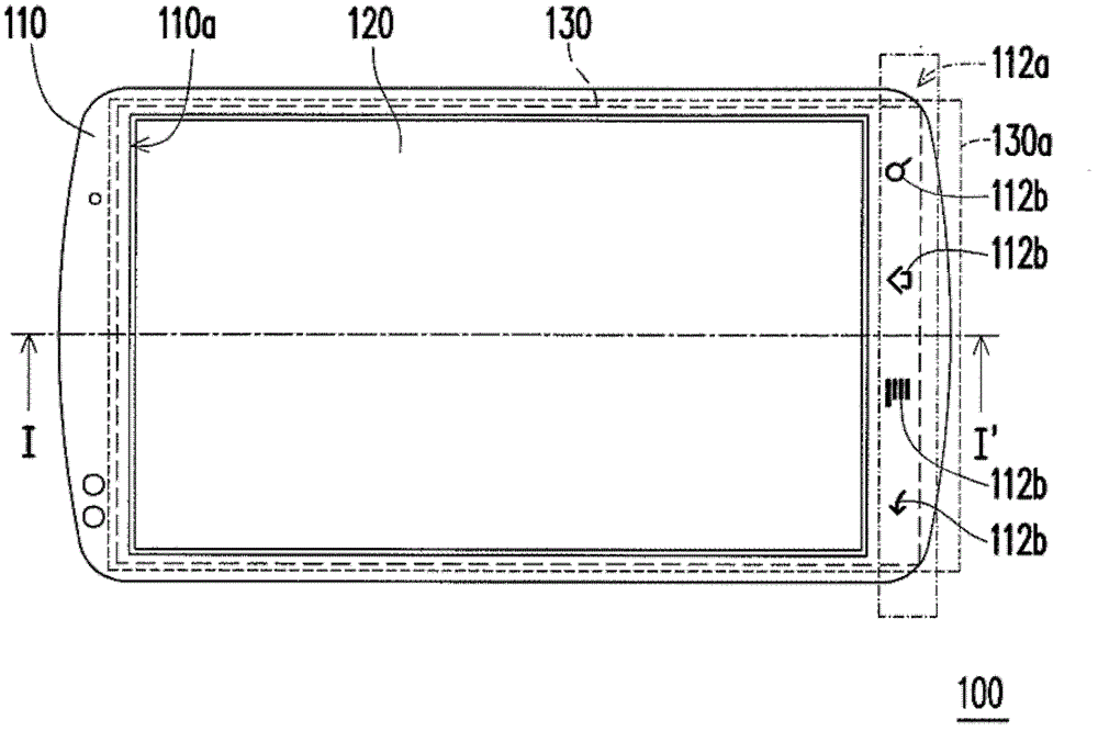
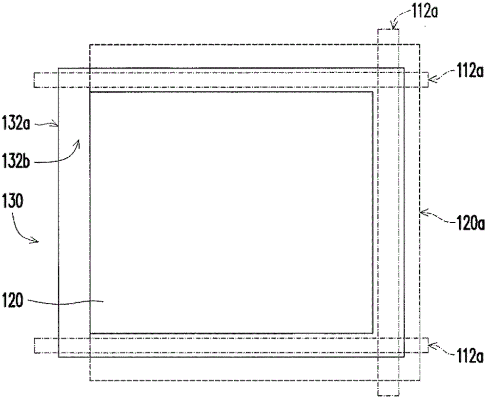
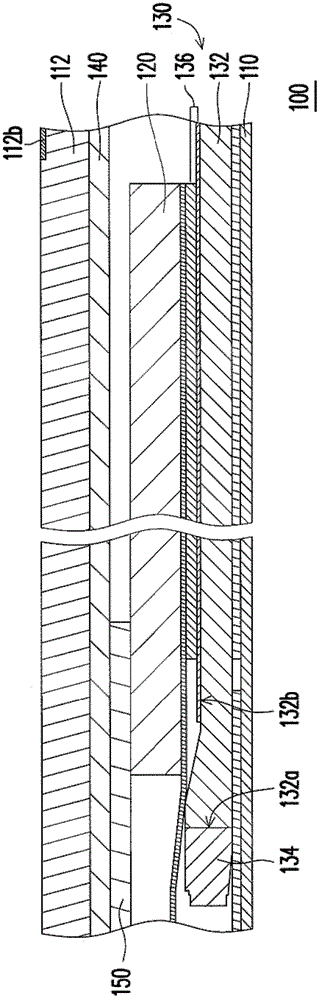
[0036] figure 1 It is a schematic diagram of a handheld electronic device according to an embodiment of the present invention. figure 2 for figure 1 The schematic diagram of the display panel and backlight module. Please refer to figure 1 and figure 2 , in this embodiment, the handheld electronic device 100 includes a casing 110 , a display panel 120 and a backlight module 130 . The casing 110 has a display opening 110a and a light-transmitting area 112a outside the display opening 110a. The display panel 120 is disposed on the display opening 110a. The backlight module 130 is disposed in the casing 110 . The backlight module 130 has a light-emitting area 130a located below the display panel 120 to provide a surface light source to the display panel 120, and the light-emitting area 130a also extends beyond the display panel 120, so that part of the surface light source is emitted out of the casing through the light-transmitting area 112a 110. Thus, the light-emitting...


PUM


Abstract

A handheld electronic device including a housing, a display panel and a backlight module is provided. The housing has a display opening and a transparent region located outside of the display opening. The display panel is disposed in the display opening. The backlight module is disposed in the housing. The backlight module has a light emitting region which is located under the display panel, adapted to provide a plane light source to the display panel. The light emitting region further extends to outside of the display panel so that a part of the plane light source is sent out the housing through the transparent region.

Description

technical field [0001] The present invention relates to a handheld electronic device, and in particular to a handheld electronic device using a backlight module to provide a display light source. Background technique [0002] A handheld electronic device refers to an electronic device that can be carried and operated by a user. Handheld electronic devices usually have small volume and weight, so that users can carry them around. Common handheld electronic devices include mobile phones, multimedia players, personal digital assistants, handheld game consoles, handheld satellite navigation and notebook computers, etc. [0003] Taking a mobile phone as an example, generally several buttons are arranged outside the display area of ​​the display panel, and light emitting diodes are correspondingly arranged under the buttons for lighting the buttons. However, these LEDs for illuminating the keys will increase the manufacturing cost of the handheld electronic device. In addition,...

Claims


Application Information

Patent Timeline
Patent Type & Authority Applications(China)
IPC IPC(8): F21S8/00F21V13/00F21V17/00F21Y101/02
CPCG02B6/006G02F1/133615G02F1/133626
Inventor 郑渊升蔡荣源江玮煌
Owner HTC CORP
Why Eureka
Try Eureka