
T-type high pier cast-in-place bent cap formwork structure and construction method

A technology of covering beams and cast-in-place, applied in bridges, bridge materials, bridge construction, etc., can solve the problems of inconvenient installation and dismantling, low safety, and many safety threats, so as to reduce earthwork leveling, speed up construction, and avoid safety risks. Effect

Inactive Publication Date: 2017-08-29
HANGZHOU JIANGRUN TECH LIMITED
View PDF0 Cites 5 Cited by
  • Summary
  • Abstract
  • Description
  • Claims
  • Application Information

AI Technical Summary

Problems solved by technology

Due to the limited space of urban overpasses, there are often line crossings. The terrain of bridges in mountainous areas is rugged and the geological conditions are different. , personnel, great investment
The hoop support method is suitable for the construction of round pier column cap beams with large heights or poor foundations. However, for the case of huge cap beam structures, the conventional hoop support method also has obvious disadvantages: ① Using a simplified model for manual calculation, the result Large dead weight, many bolts, inconvenient installation and removal
③Because the hoop has no floor support, the whole support generally has a large truss main beam and a large number of steel secondary beams. The installation and removal of the support requires a lot of high-altitude lifting operations and mechanical shifts, which poses many safety threats

Method used


Image

  • T-type high pier cast-in-place bent cap formwork structure and construction method
  • T-type high pier cast-in-place bent cap formwork structure and construction method
  • T-type high pier cast-in-place bent cap formwork structure and construction method

Examples


Embodiment Construction

[0034] The present invention will be further described below in conjunction with the accompanying drawings of the description.

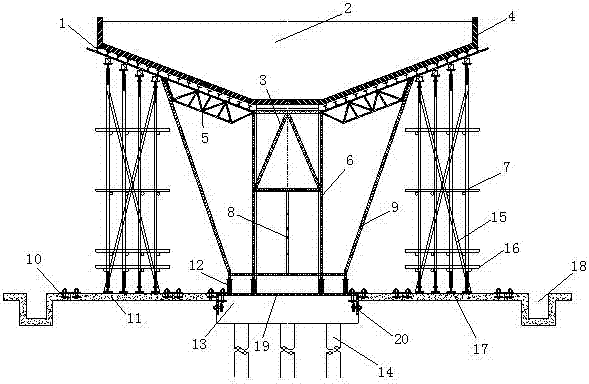
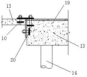
[0035] Such as Figure 1-4 As shown, a T-shaped high pier cast-in-place cover beam formwork structure and construction method, including I-shaped steel 1, cast-in-place cover beam 2, well-shaped support diagonal brace 3, shaped steel formwork 4, shaped steel frame 5, well Font bracket 6, bowl button bracket 7, adjusting bolt 8, bracket pole 9, prefabricated reinforced concrete slab embedded bolt 10, prefabricated reinforced concrete backing plate 11, jack 12, cap 13, pier pile 14, scissors support 15. Sweeping pole 16, quick assembly and disassembly joint of vertical pole 17, prefabricated reinforced concrete drainage ditch 18, steel plate frame grating 19, embedded parts of platform cap 20, bolt holes 21, shaped steel frame vertical bar 22, shaped steel frame Upper chord 23, shaped steel frame lower chord 24 and shaped steel frame inclined bar 25. ...


PUM


Abstract

The invention discloses a T-type high pier cast-in-place bent cap formwork structure. The T-type high pier cast-in-place bent cap formwork structure comprises a cushion cap, a steel plate frame latticed panel is arranged at the top of the cushion cap, prefabricated reinforced concrete base plates are fixedly connected to the two ends, a groined support is arranged on the upper portion of the steel plate frame latticed panel, a shaped steel formwork is arranged on the upper portion of the groined support, and support vertical rods are connected to the two ends of the groined support; a shaped steel frame is arranged between the top of the groined support and the tops of the support vertical rods and is fixedly connected with the groined support and the support vertical rods, and joist steel is arranged between the shaped steel frame and the shaped steel formwork; upside down bowl-type brackets are arranged on the upper portion of the prefabricated reinforced concrete base plates. The T-type high pier cast-in-place bent cap formwork structure has the advantages that the existing cushion cap and prefabricated reinforced concrete plate concrete are used as bearing bases, the work of earthwork flattening and foundation hardening is reduced, foundation processing mechanical cost, concrete material cost and labor cost are saved, and the engineering period is shortened.

Description

technical field [0001] The invention relates to the technical field of bridge engineering, in particular to a T-shaped high pier cast-in-place cover beam formwork structure and a construction method. Background technique [0002] Bridge engineering is an important way to modernize the road traffic system. Overpasses, light rail viaducts, high-speed rail and train track viaducts in cities are all part of the road traffic system. Pier cap beam construction is a commonly used technology in bridge construction, but due to the high technical level requirements, the cast-in-place structure of supports is a more commonly used structural form in bridge structures. [0003] At present, there are two main types of formwork support forms for cover beam construction: floor support and non-floor support. The non-floor support is not erected by the ground, but a suspended formwork support that is erected by using the poured pier column structure to form a corbel near the top of the pier ...

Claims


Application Information

Patent Timeline
IPC IPC(8): E01D21/00E01D101/28
CPCE01D21/00E01D2101/28
Inventor 王新泉
Owner HANGZHOU JIANGRUN TECH LIMITED
Learn More