Tunnel lining construction method

A construction method and tunnel technology, which is applied in the direction of tunnel lining, tunnel, shaft lining, etc., can solve the problem that the flatness of the concrete layer of the support structure is difficult to control, the overall durability of the lining cannot reach the design service life, and it is difficult to ensure the welding seam Quality and effect and other issues, to achieve the effect of improving sprayability, superior performance, and reducing surface shrinkage microcracks

Active Publication Date: 2014-03-26
POWERCHINA HEBEI ELECTRIC POWER SURVEY & DESIGN INST CO LTD
View PDF5 Cites 6 Cited by
  • Summary
  • Abstract
  • Description
  • Claims
  • Application Information

AI Technical Summary

Problems solved by technology

[0003] In the construction process of composite lining structure, hanging steel mesh is a time-consuming and dangerous work, and the existence of steel mesh will lead to high rebound rate of shotcrete, resulting in waste of materials, large amount of steel, concrete and other materials, and high cost. High, complex construction process, long construction period
[0004] Due to the existence of the steel mesh, the shotcrete cannot fit well with the excavation surface, and a cavity must be formed between the steel mesh and the excavation surface, leaving a hidden danger for the corrosion of the steel mesh
The structural protrusions on the steel mesh and the spraying construction process make it difficult to control the flatness of the concrete layer of the initial support structure, resulting in a poor base surface for laying the waterproof layer, which is easy to cause damage to the waterproof layer itself. In addition, due to construction reasons, the waterproof layer rolls. It is difficult to ensure the quality and effect of the weld seam in the stubble-joining process of the material, and these factors are likely to leave hidden dangers of water leakage
Due to the existence of these safety hazards, the lining is prone to cracking and leakage after the tunnel is completed and operated, resulting in the overall durability of the lining not reaching the design service life

Method used


Image

  • Tunnel lining construction method

Examples


Embodiment Construction

[0019] Below in conjunction with accompanying drawing, the present invention is described in further detail:

[0020] A tunnel lining construction method specifically comprises the following steps:

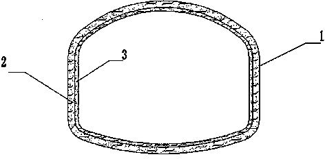
[0021] A. Excavate the cavern first, and construct full-section steel arches 1 at intervals along the excavation surface of the surrounding rock in the longitudinal direction of the tunnel in the cavern, and the distance between adjacent steel arches 1 is 750mm.

[0022] B. Stir the low-carbon fiber concrete, spray low-carbon fiber concrete with a thickness of 20mm±1mm on the excavation surface of the surrounding rock between the adjacent steel arches 1 with a wet sprayer to form the inner concrete layer 2.

[0023] The low-carbon fiber concrete of the present invention is formed by mixing fly ash and silica fume into ordinary shotcrete, and then adding steel fibers and polypropylene fibers. The prepared low-carbon fiber concrete includes per cubic meter 53.1 Kg~106.2 Kg of fly a...


PUM


Abstract

The invention discloses a tunnel lining construction method which includes the following steps: constructing full-fracture-surface steel arches along the longitudinal surrounding rock excavation face of a tunnel at intervals, spraying two layers of low-carbon type fiber concrete layers at the position, between adjacent steel arches, of the surrounding rock excavation face at a high speed with a wet spraying machine depending on air pressure, and forming a tunnel lining structure until the tunnel is through. The tunnel lining construction method is simple in construction process and safe in construction procedure, the sprayed concrete rebound rate can be lowered, the spraying performance is improved, the energy consumption is reduced, and the formed tunnel lining structure is high in toughness, good in anti-permeability, good in durability and particularly suitable for weak surrounding rock tunnel supports constructed with the mining method.

Description

technical field [0001] The invention relates to the field of tunnels, in particular to a construction method for tunnel lining. Background technique [0002] Lining is a permanent support structure built with reinforced concrete and other materials along the periphery of the tunnel body to prevent the surrounding rock from deforming or collapsing. The existing tunnel lining usually adopts composite lining structure, including primary support, waterproof layer and secondary lining. Composite lining is a tunnel lining constructed in two layers, inside and outside. After the excavation of the cavern, the steel arch frame is placed first, the steel mesh is hung, and then the shotcrete that is close to the surrounding rock is applied as the outer surface of the primary support. After the deformation of the surrounding rock is basically stable, the molded reinforced concrete inner layer lining will be applied, and a waterproof layer will be set between the two layers of lining. ...

Claims


Application Information

Patent Timeline
Patent Type & Authority Applications(China)
IPC IPC(8): E21D11/00E21D11/10C04B18/08C04B16/06C04B14/48
CPCY02W30/91
Inventor 赵怀宇李占岭孟金波
Owner POWERCHINA HEBEI ELECTRIC POWER SURVEY & DESIGN INST CO LTD
Why Eureka
Try Eureka