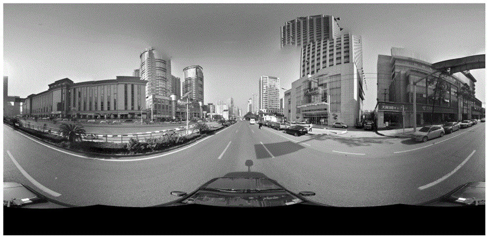
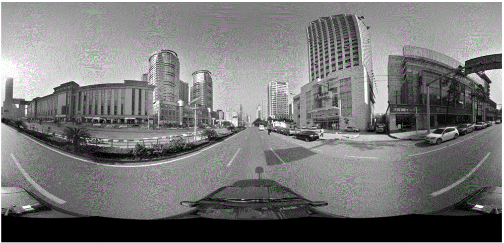
Image stitching processing method and device
An image stitching and processing method technology, applied in the field of image processing, can solve problems such as stitching gaps, achieve the effects of small stitching gaps, uniform error dispersion, and improved stitching quality
- Summary
- Abstract
- Description
- Claims
- Application Information
AI Technical Summary
Problems solved by technology
Method used
Image
Examples
no. 1 example
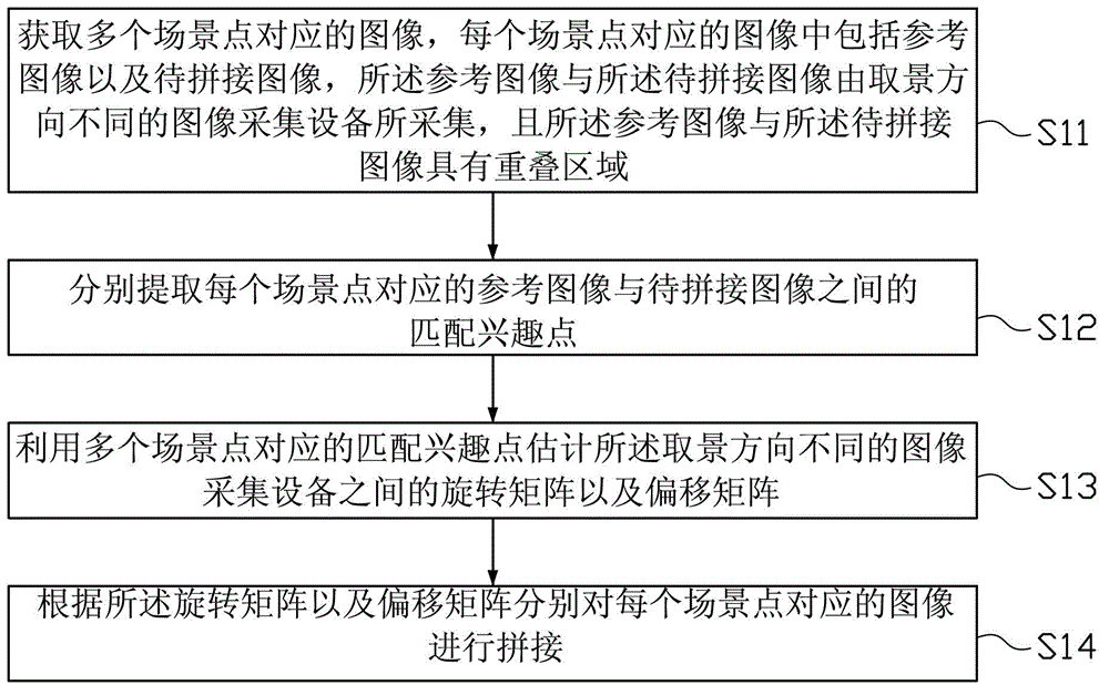
[0020] figure 2 This is a schematic flowchart of the image stitching processing method in the first embodiment of this application. Such as figure 2 As shown, the image stitching processing method in this embodiment includes:
[0021] Step S11: Obtain images corresponding to multiple scene points. The image corresponding to each scene point includes a reference image and an image to be spliced. The reference image and the image to be spliced are collected by image acquisition devices with different viewing directions, and The reference image and the image to be spliced have an overlapping area.
[0022] In the embodiments of the present application, the images corresponding to the same scene point are derived from images collected by image acquisition devices (including cameras, image sensors, etc.) with different viewing directions of the same scene at the same shooting point. The shooting point refers to the shooting location of the image, that is, the geographic location ...
no. 2 example
[0035] Figure 4 This is a schematic flowchart of the image stitching processing method in the second embodiment of this application. Such as Figure 4 As shown, the image stitching processing method in this embodiment includes:
[0036] Step S21: Acquire images corresponding to a plurality of scene points, the image corresponding to each scene point includes a reference image and an image to be spliced, the reference image and the image to be spliced are collected by image acquisition devices with different viewing directions, and The reference image and the image to be spliced have an overlapping area. This step is the same as the corresponding step in the first embodiment, and will not be repeated here.
[0037] Step S22: Extract the matching interest points between the reference image corresponding to each scene point and the image to be spliced.
[0038] In this embodiment, step S22 may further include:
[0039] Step S221: preprocessing the reference image corresponding to ...
no. 3 example
[0057] Figure 5 This is a schematic structural diagram of an image stitching processing device in the third embodiment of this application. Such as Figure 5 As shown, the image stitching processing device 30 in this embodiment can implement the image stitching processing method in the first embodiment of the present application. The image stitching processing device 30 may specifically include: an image acquisition module 31, a matching interest point extraction module 32, and a matrix The calculation module 33 and the image stitching module 34.
[0058] The image acquisition module 31 is used to acquire images corresponding to multiple scene points. The image corresponding to each scene point includes a reference image and an image to be spliced. The reference image and the image to be spliced are captured by image acquisition devices with different viewing directions. Collecting, and the reference image and the image to be stitched have an overlapping area. The matching in...
PUM
 Abstract
Description
Claims
Application Information
 - R&D
- Intellectual Property
- Life Sciences
- Materials
- Tech Scout
- Unparalleled Data Quality
- Higher Quality Content
- 60% Fewer Hallucinations
Browse by: Latest US Patents, China's latest patents, Technical Efficacy Thesaurus, Application Domain, Technology Topic, Popular Technical Reports.
© 2025 PatSnap. All rights reserved.Legal|Privacy policy|Modern Slavery Act Transparency Statement|Sitemap|About US| Contact US: help@patsnap.com


