Automatic splicing conveying auxiliary device of wire cord fabric cutting machine and conveying method thereof

A steel cord, automatic splicing technology, applied to tires, other household appliances, household appliances, etc., can solve the problems of poor head and tail alignment of steel cord, splicing deviation, difficult head and tail alignment, etc., to reduce manual assistance time. , Improve the accuracy, prevent the effect of skew

Active Publication Date: 2016-03-30
桂林中昊力创机电科技有限公司
View PDF3 Cites 4 Cited by
  • Summary
  • Abstract
  • Description
  • Claims
  • Application Information

AI Technical Summary

Problems solved by technology

[0005] The main disadvantage of the above-mentioned splicing device is that it is difficult to align the head of the rear steel cord with the tail of the previous steel cord due to the influence of different conveyor belt resistances
[0006] The reason is: the steel cord is conveyed from the feeding conveying device to the splicing conveyor belt. Since the steel cord slides relative to the stationary splicing conveyor belt surface, for the steel cord with too long hypotenuse or the cutting angle is greater than 45°, the steel cord head Poor tail alignment, resulting in splicing deviations

Method used


Image

  • Automatic splicing conveying auxiliary device of wire cord fabric cutting machine and conveying method thereof
  • Automatic splicing conveying auxiliary device of wire cord fabric cutting machine and conveying method thereof
  • Automatic splicing conveying auxiliary device of wire cord fabric cutting machine and conveying method thereof

Examples


Embodiment Construction

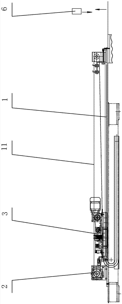
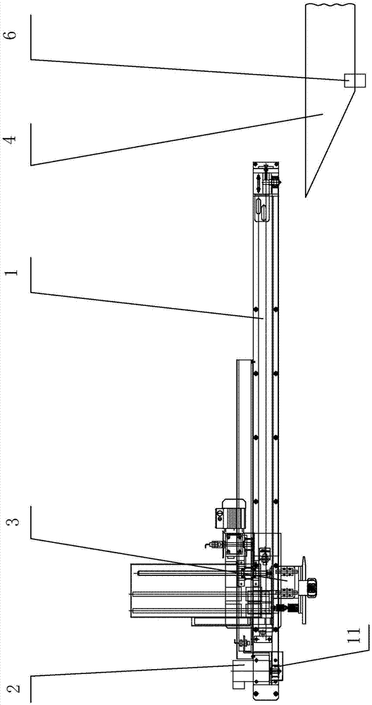
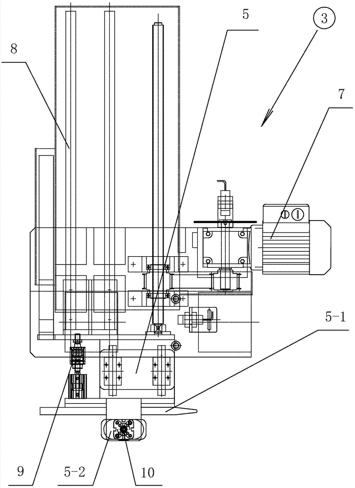
[0026] The technical solutions of the present invention will be further described below in conjunction with the embodiments shown in the accompanying drawings.

[0027] The automatic splicing and feeding auxiliary device of the steel cord cutting machine of the present invention includes a linear guide rail mechanism 1, a servo control system 2, a magnetic adsorption mechanism 3 and a sensor 6. The straight side and the same side) are arranged along the conveying direction of the steel cord 4. The servo control system 2 is set at one end of the linear guide rail mechanism 1 and is driven to move back and forth on the linear guide rail mechanism 1 through the synchronous belt drive pair 11. The magnetic adsorption mechanism 3 Install the linear guide rail assembly 8 (horizontally) on the linear guide rail mechanism 1 perpendicular to the conveying direction of the steel cord 4, and drive the servo motor drive mechanism 7 to move back and forth on the linear guide rail assembly 8...


PUM


Abstract

The invention discloses an automatic splicing conveying auxiliary device of a wire cord fabric cutting machine. The automatic splicing conveying auxiliary device comprises a linear guide rail mechanism arranged in a conveying direction and a magnetic adsorption mechanism driven by a servo control system to reciprocate on the linear guide rail mechanism; the magnetic adsorption mechanism comprises a magnetic adsorption head arranged on an acute-angle straight side edge of a wire cord fabric to adsorb the head of the wire cord fabric, and a servo motor driving mechanism for automatically adjusting a position of the magnetic adsorption head on a linear guide rail mechanism perpendicular to the conveying direction of the wire cord fabric according to a sensor feedback signal of detecting a position of the other straight side edge of the wire cord fabric; a conveying method of the automatic splicing conveying auxiliary device comprises the following steps that: the magnetic adsorption head adsorbs a wire cord fabric to a seaming position at a constant conveying speed; after releasing the wire cord fabric, the magnetic adsorption head returns to an initial position to wait for delivery of next wire cord fabric, and the process is circulated continuously until conveying and splicing of the wire cord fabrics are completed automatically. The automatic splicing conveying auxiliary device of the wire cord fabric cutting machine has the advantages of improving the accuracy of butting of heads and tails of wire cord fabrics, improving the quality of splicing, improving the reliability of equipment and reducing artificial auxiliary time.

Description

technical field [0001] The invention relates to tire semi-finished product production equipment, in particular to an automatic splicing and feeding auxiliary device and a feeding method for a steel cord cutting machine. Background technique [0002] In the existing manufacturing process of all kinds of all-steel and semi-steel tires, it is necessary to cut, joint and bond the various rubber parts constituting the tire, so as to form the structure of the crown and sidewall of the tire. [0003] At present, the traditional steel cord cutting machine cutting and splicing scheme includes a feeding conveying device before splicing, an independent splicing conveyor belt, a splicing device and a splicing unloading device. [0004] The conventional cutting and splicing scheme is: the feeding and conveying device before splicing conveys the head of the cut steel cord to the static splicing conveyor belt, and connects with the tail of the previous piece of steel cord positioned on the...

Claims


Application Information

Patent Timeline
Patent Type & Authority Applications(China)
IPC IPC(8): B29D30/38B29D30/46
CPCB29D30/38B29D30/46
Inventor 李德昌蒋海龙赵兴军
Owner 桂林中昊力创机电科技有限公司
Why Eureka
Try Eureka