Elastic connection mechanism for automatic transfer switch device
An automatic transfer switch and elastic connection technology, applied in the direction of electric switches, electrical components, circuits, etc., can solve the problems of cumbersome manufacturing and maintenance, complex structure of centrifugal switches, prone to failure, etc., and achieve stable and reliable working performance and reasonable and simplified structure , the effect of fewer failure sources
- Summary
- Abstract
- Description
- Claims
- Application Information
AI Technical Summary
Problems solved by technology
Method used
Image

Examples
Embodiment 1)
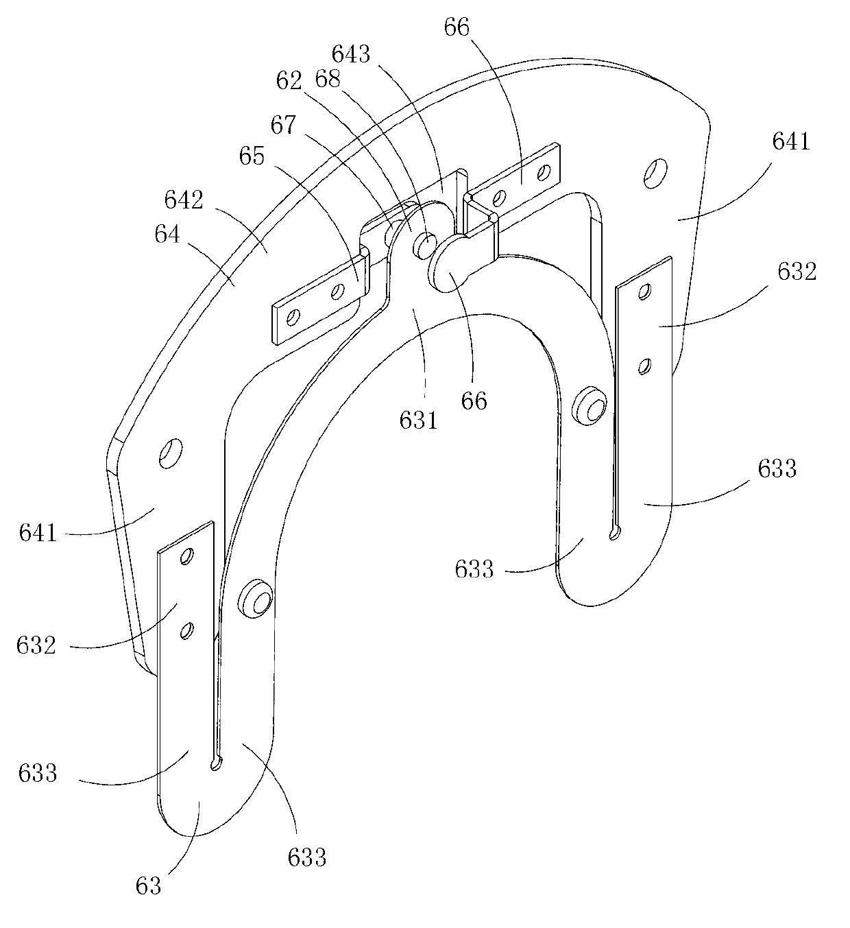
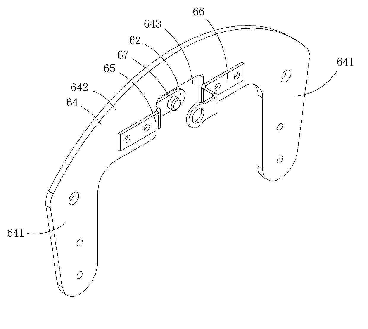
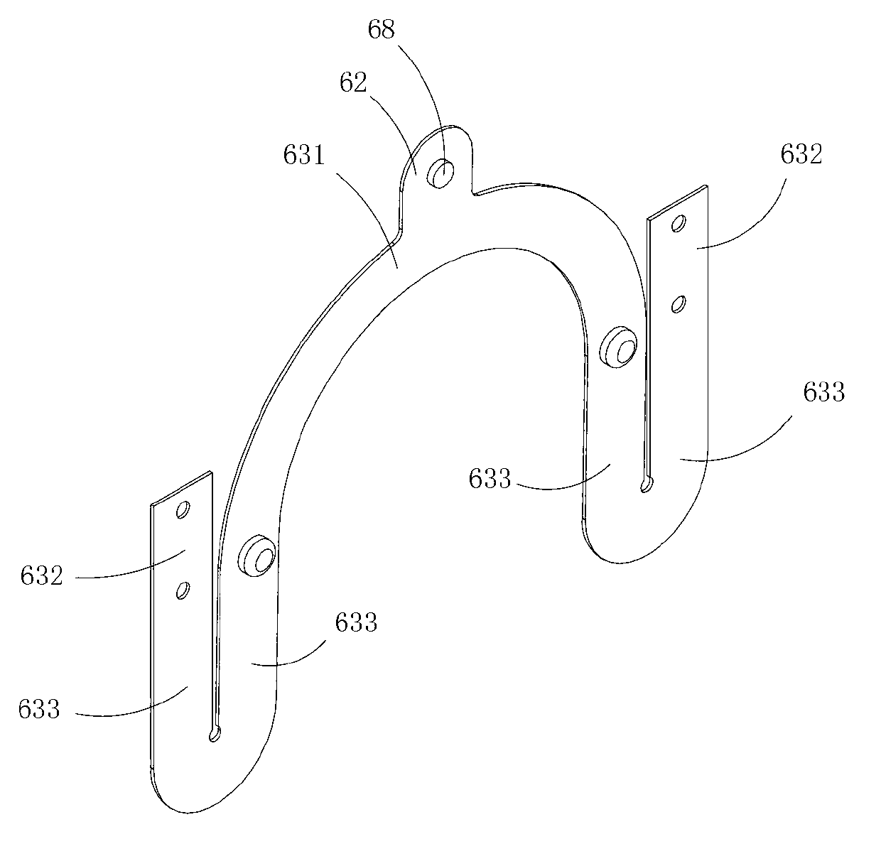
[0015] Figure 1 to Figure 3 A first embodiment of the invention is shown, in which figure 1 It is a schematic diagram of a three-dimensional structure of the present invention; figure 2 for figure 1 A schematic diagram of a three-dimensional structure of the insulating fixing plate in the elastic connection mechanism shown; image 3 for figure 1 A schematic diagram of a three-dimensional structure of the elastic member in the elastic connection mechanism shown.
[0016] This embodiment is a kind of elastic connecting mechanism used in automatic transfer switch device, see Figure 1 to Figure 3 , including an elastic member 63 provided with a movable contact 62, and an insulating fixing plate 64 provided with a first static contact 65 and a second static contact 66; the movable contact is located between the first static contact and the second static contact Between the contacts; the basic shape of the insulating fixing plate is U-shaped, including two connection areas 6...
PUM
 Abstract
Description
Claims
Application Information
 - Generate Ideas
- Intellectual Property
- Life Sciences
- Materials
- Tech Scout
- Unparalleled Data Quality
- Higher Quality Content
- 60% Fewer Hallucinations
Browse by: Latest US Patents, China's latest patents, Technical Efficacy Thesaurus, Application Domain, Technology Topic, Popular Technical Reports.
© 2025 PatSnap. All rights reserved.Legal|Privacy policy|Modern Slavery Act Transparency Statement|Sitemap|About US| Contact US: help@patsnap.com