Anti-collision control method of fixture

A control method and anti-collision technology, which is applied in the direction of clamping, manufacturing tools, grinding machine tool parts, etc., can solve problems such as collisions, affecting product accuracy, and equipment damage

Active Publication Date: 2020-10-27
广西现代职业技术学院
View PDF8 Cites 1 Cited by
  • Summary
  • Abstract
  • Description
  • Claims
  • Application Information

AI Technical Summary

Problems solved by technology

[0003] The invention provides an anti-collision control method of a fixture, which can solve the problem that the clamping objects of the existing fixture or the operating platform or the robot are collided, causing damage to the equipment and affecting the accuracy of the product

Method used


Image

  • Anti-collision control method of fixture
  • Anti-collision control method of fixture
  • Anti-collision control method of fixture

Examples


Embodiment 1

[0027] The present invention will be described in further detail below in conjunction with accompanying drawing embodiment:

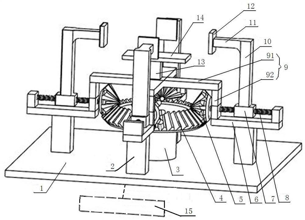
[0028] figure 1 , figure 2 The shown multi-directional anti-collision fixture includes a conical bull gear 4 arranged on the installation base 1 and a bracket 9 spanning above the conical bull gear 4, and an enclosure between the installation base 1 and the conical bull gear 4 is provided. To the bevel gear drive motor 3 in the middle of the support foot 2, the bevel gear 4 is meshed with two pairs of bevel pinion gears 5; each pair of bevel pinion gears 5 is relatively arranged; wherein, the support 9 includes two cross bars 91 and Four vertical rods 92 protruding downward from the two ends of the respective cross rods 91; the vertical rods 92 are connected with the respective screw bases 6; The screw shafts 8 of the respective conical pinions are provided on the screw bases 6, and each conical pinion 5 is set on one end of the respective screw shaf...

Embodiment 2

[0035] Such as Figure 6 As shown, the driving device includes an X-direction rack 251 meshing with an X-direction gear 254, a Y-direction rack 252 meshing with a Y-direction gear 255, and a Z-direction rack 253 meshing with a Z-direction gear 256; There are two racks 252 parallel to each other, and the two Y racks 252 are installed on the frame through their respective Y rack seats; a mounting plate 250 for the X racks is arranged between the Y racks 252, The mounting plate 250 is provided with a long through hole for wearing the Z-direction rack 253 in the same direction as the X-direction rack 251; the top of the Z-direction rack 253 is fixedly connected to the mounting base plate of the fixture; the drive motor includes an X-direction gear drive motor 257. The Y-direction gear drive motor 258 and the Z-direction gear drive motor 259; the output shaft of the X-direction gear drive motor 257 is set on the core hole of the X-direction gear 254, and the output shaft of the Y-d...

Embodiment 3

[0038] Such as Figure 7 As shown, the driving device is the mechanical arm 331 of the robot, and the hand joint of the mechanical arm is fixedly connected with the installation base plate of the fixture; the operating claw 332 of the robot is connected with the mounting plate of the object to be clamped; the controller is located in the robot body; the driving motor is The mechanical arm drive motor; the signal output end of the PLC programmable control module is respectively connected with the mechanical arm drive motor through the second drive module; all the others are the same as the first embodiment;

[0039] Its anti-collision control method is: when the real-time signals sensed by the horizontal anti-collision sensor and the vertical anti-collision sensor exceed the preset value in the controller, it means that the clamped operating claw is collided in an oblique direction. At this time, the controller will After the received signal is judged and processed, the corresp...


PUM


Abstract

The invention discloses an anti-collision control method of a clamp, and belongs to the technical field of mechanical manufacturing. The method adopts a multidirectional anti-collision clamp, the clamp comprises a transverse anti-collision sensor arranged between a chuck supporting column and a chuck of the clamp and a vertical anti-collision sensor arranged between the middle of a support of theclamp and a mounting plate of the object to be clamped; a driving device is arranged at the bottom end of the mounting bottom plate of the clamp; the anti-collision control method comprises the following steps that when the external collision signals sensed by the vertical anti-collision sensor and / or the transverse anti-collision sensor in real time exceeds a preset value range in the controller,the controller controls the driving device to drive the clamping object to move towards the direction of unloading collision force after the received external collision signals are judged and processed. According to the anti-collision control method, the problems of equipment damage and product precision influence caused by collision of a clamping object or an operation platform or a robot of anexisting clamp can be solved.

Description

technical field [0001] The invention relates to the technical field of mechanical manufacturing, in particular to an anti-collision control method for fixtures in industrial production. Background technique [0002] Various fixtures are often used in industrial production. Since there are a lot of equipment placed in the workshop, and the production process is a dynamic process, it is often the case that the clamped objects of the fixture are collided and affect the production or even damage the equipment. At the same time In a production workshop with a high degree of intelligence, because multiple manipulators process parts on the operating platform at the same time or multiple robots are continuously performing various operating movements at the same time, there will also be conflicts between the manipulator and the operating platform. In the unexpected situation of collision or robot collision, once the collision between the manipulator and the operation platform or the ...

Claims


Application Information

Patent Timeline
Patent Type & Authority Patents(China)
IPC IPC(8): B23Q3/06B24B41/06B24B47/22
CPCB23Q3/06B24B41/06B24B47/22
Inventor 涂翔宇刘正奇李观生班华香陈田波
Owner 广西现代职业技术学院
Why Eureka
Try Eureka