Manipulator collision prompting device

A technology of manipulators and warning devices, applied in manipulators, program-controlled manipulators, manufacturing tools, etc., can solve problems such as inability to grade warnings and collisions that cannot serve as warnings.

Active Publication Date: 2020-10-27
WUHAN ZNION TECH CO LTD
View PDF11 Cites 0 Cited by
  • Summary
  • Abstract
  • Description
  • Claims
  • Application Information

AI Technical Summary

Problems solved by technology

When the longitudinal axis of the manipulator goes down and the workpiece grabbing unit interferes with the machine tool fixture, the vertical sliding mechanism drives the workpiece grabbing unit to move upward and out of the detection range of the anti-collision detection unit. At this time, the controller will cut off the power switch of the manipulator. Avoid damage caused by the collision between the workpiece grabbing unit and the machine tool, that is, the device can only achieve anti-collision in the vertical direction, and cannot serve as a warning for possible collisions in other directions. Secondly, it can only play a role in a single degree of collision interference. Anti-collision function, unable to provide graded warnings according to the severity of the collision

Method used


Image

  • Manipulator collision prompting device
  • Manipulator collision prompting device
  • Manipulator collision prompting device

Examples


Embodiment 1

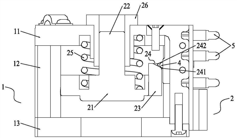
[0030] A kind of manipulator collision warning device, see figure 1 , including a frame 1 and an anti-collision assembly 2 arranged in a support mechanism, the frame 1 includes an upper panel 11, a lower panel 13 and a fixed column 12 arranged between the upper and lower panels 13, the fixed column 12 It is used to fixedly connect the upper and lower panels 13 to form a rectangular frame. The anti-collision assembly 2 is arranged in the cavity surrounded by the rectangular frame. The anti-collision assembly 2 includes a support plate 21 fixed to the top of the support plate 21. The connected slide bar 22 and the pressing plate 23 fixed on the edge of the support plate 21, the top end of the slide bar 22 is located in the frame 1 and is slidingly fitted with the frame 1, the outside of the slide bar 22 A spring 25 is sleeved, and the two ends of the spring 25 abut against the frame 1 and the support plate 21 respectively. Specifically, the center of the upper panel 11 is provid...

Embodiment 2

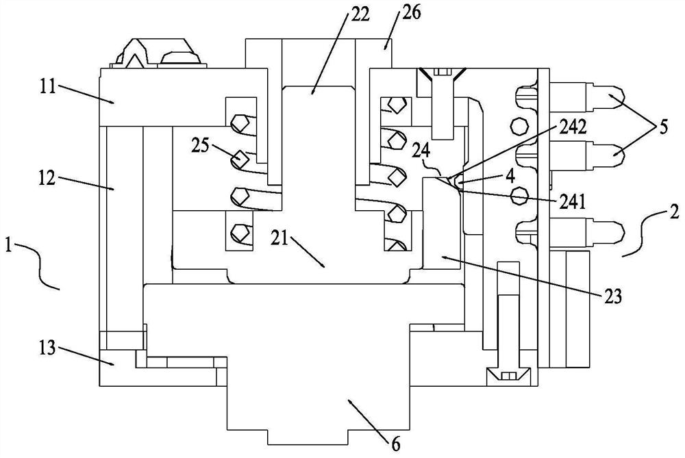
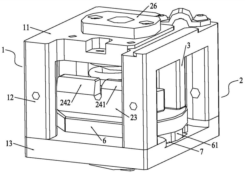
[0034] Embodiment 2 is basically the same as Embodiment 1, and its difference is: see Figure 2-6 A T-shaped movable plate 6 rests between the lower panel 13 of the frame 1 and the support plate 21, and the lower end of the movable plate 6 passes through the bottom of the frame 1 and can rotate relative to the frame 1 , the lower end of the movable plate 6 is connected to a power load. That is, the movable plate 6 is located below the support plate 21 and rests on the lower panel 13, the lower end of the movable plate 6 protrudes from the lower panel 13 and is rotatably connected with the lower panel 13, Therefore, the movable plate 6 can move up and down and deflect vertically relative to the lower panel 13 and the support plate 21 . In order to prevent the movable plate 6 from deflecting excessively, a fan-shaped groove 7 is formed on the lower panel 13 of the frame 1, and a fan-shaped protrusion 61 matching the shape of the groove is formed on the bottom of the movable pla...

Embodiment 3

[0038] Embodiment 3 is basically the same as embodiment 1 or embodiment 2, and its difference is: see Figure 7 A plurality of the contact switches 4 are vertically distributed side by side, and at this time, the pressing plate 23 may only have one inclined surface 24 . By being arranged side by side, the distances between a plurality of the contact switches 4 and the inclined surface 24 are different, and the moving distance of the pressing plate 23 is related to the collision force. Therefore, different warning devices are respectively activated by pressing the moving distance of the pressing plate 23. 5. Realize hierarchical touch warning.


PUM


Abstract

The invention discloses a manipulator collision prompting device, and belongs to the technical field of manipulator production and manufacturing. The manipulator collision prompting device particularly comprises a rack and an anti-collision assembly arranged in a supporting mechanism, wherein the anti-collision assembly comprises a supporting plate, a sliding rod fixedly connected with the top ofthe supporting plate and a pressing plate fixedly arranged on the edge of the supporting plate, the top end of the sliding rod is located in the rack and is in sliding fit with the rack, the outer side of the sliding rod is sleeved with a spring, the two ends of the spring abut against the rack and the supporting plate, a plurality of contact switches are arranged at the positions, corresponding to the pressing plate, of the rack, the plurality of contact switches are connected with warning devices in corresponding states, and the warning devices are controlled to perform graded warning according to the fact that the pressing plate touches the contact switches. According to the manipulator collision prompting device, different contact switches are pressed by moving the pressing plate by different distances, then different warning devices are started, and the graded touch warning effect can be effectively achieved.

Description

technical field [0001] The invention relates to the technical field of manipulator manufacturing, in particular to a manipulator collision prompting device. Background technique [0002] In industrial automation production, the application of manipulator is more common. Manipulator is an automatic operation device that can imitate certain movement functions of human hands and arms, and is used to grab, carry objects or operate tools according to a fixed program. The feature is that various expected operations can be completed through programming, and the structure and performance have both the advantages of man and robot. However, fast-running manipulators have strong kinetic energy. Due to high-speed movement, a slight change in position will cause severe collisions, and often lead to collisions between mechanical parts. Long-term collisions between the manipulator and objects are likely to cause mechanical damage and reduce Product quality, or even damage to items, so it ...

Claims


Application Information

Patent Timeline
Patent Type & Authority Applications(China)
IPC IPC(8): B25J19/06B25J9/16
CPCB25J19/06B25J9/1676
Inventor 陈志文孙聪
Owner WUHAN ZNION TECH CO LTD
Why Eureka
Try Eureka