Electric vehicle battery with series and parallel fluid flow

A fluid flow, fluid technology used in the field of electric vehicle batteries with continuous and parallel fluid flow

Active Publication Date: 2013-06-12
FORD GLOBAL TECH LLC
View PDF3 Cites 0 Cited by
  • Summary
  • Abstract
  • Description
  • Claims
  • Application Information

AI Technical Summary

Problems solved by technology

[0006] Proposed continuous/parallel bypass configuration of heat transfer flui

Method used


Image

  • Electric vehicle battery with series and parallel fluid flow
  • Electric vehicle battery with series and parallel fluid flow
  • Electric vehicle battery with series and parallel fluid flow

Examples


Embodiment Construction

[0024] A detailed description of the illustrated embodiments is provided below. The illustrated embodiments are examples that can be embodied in various and alternative forms. The drawings are not necessarily to scale. Some features may be exaggerated or minimized to show details of particular components. Specific structural and functional details disclosed in this application are not to be interpreted as limiting, but merely as a representative basis for teaching one skilled in the art how to practice the invention.

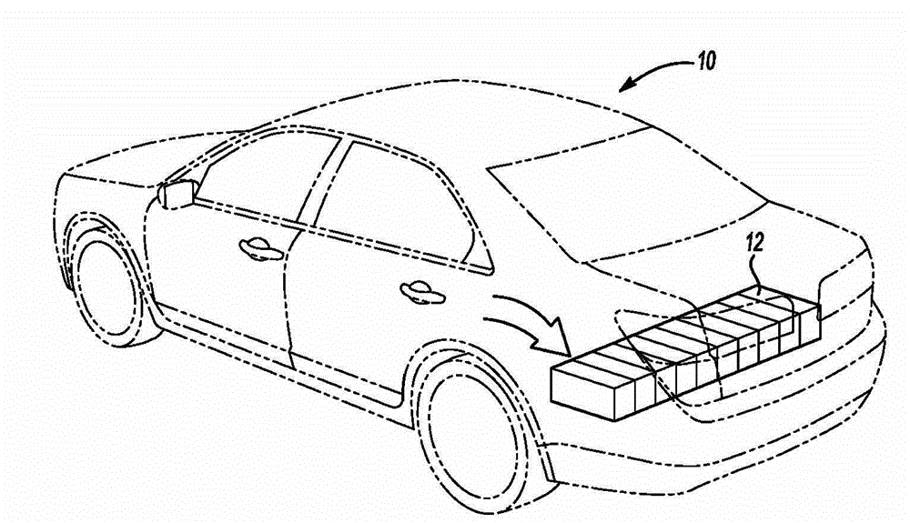
[0025] refer to figure 1 , an electric vehicle with battery pack 12 is shown in dashed lines. Electric vehicle 10 may be a plug-in electric vehicle or a hybrid electric vehicle. The electric vehicle 10 may include a high voltage battery, depicted as a battery pack 12 in the trunk of the vehicle 10 . The battery pack 12 may be located at the front of the vehicle or at another location or orientation of the vehicle 10 . Battery pack 12 may be a prismatic bat...


PUM


Abstract

A fluid cooled series/parallel battery pack is provided with a fluid flow system. A plurality of prismatic battery cells are arranged in parallel in two or more rows. Fluid flows in a series flow configuration from an upstream row of batteries to a downstream row of batteries. A bypass passageway provides additional fluid flow to an inner plenum located between the rows of batteries to reduce pressure drop and provide more uniform temperatures within the rows of battery cells.

Description

technical field [0001] The present disclosure relates to controlling the temperature and pressure differential of batteries used in electric vehicles. Background technique [0002] High-voltage battery packs composed of prismatic cells, such as lithium-ion cells, can be arranged in arrays that require cooling to operate efficiently. The battery pack can be arranged in a variety of ways, including a parallel configuration in which all of the prismatic battery cells are aligned parallel to each other. The parallel fluid cooling arrangement has a common inlet chamber that provides fluid to each battery cell and fluid into a common outlet chamber without passing through other battery cells. In a parallel arrangement, all of the cells are uniformly cooled to minimize cell-to-cell temperature differences. Parallel arrangements are difficult to package because they lead to an ever-increasing build length as the required voltage increases. Additionally, exhaust requirements can m...

Claims


Application Information

Patent Timeline
IPC IPC(8): H01M10/50
CPCH01M10/613H01M10/617H01M10/625H01M10/6566H01M10/6568Y02E60/10
Inventor 詹姆士·乔治·加比萨拉瓦南·帕拉马斯万布莱恩·尤特利乔治·艾尔伯特·加芬克尔
Owner FORD GLOBAL TECH LLC
Why Eureka
Try Eureka