Improved broadband multi-dipole antenna with frequency-independent radiation characteristics

A technology of dipoles and folded dipoles, which is applied to antenna unit combinations, antennas, antenna arrays and other directions with different polarization directions, and can solve difficult problems such as antenna performance and mechanical tolerances.

Active Publication Date: 2013-06-12
ELEVENANTENNA
View PDF5 Cites 22 Cited by
  • Summary
  • Abstract
  • Description
  • Claims
  • Application Information

AI Technical Summary

Problems solved by technology

[0010] However, it is difficult to use the antennas of WO 05/015685 and WO 05/015686 over a large frequency range due to problems of mechanical tolerances when combining small and large mechanical parts, and

Method used


Image

  • Improved broadband multi-dipole antenna with frequency-independent radiation characteristics
  • Improved broadband multi-dipole antenna with frequency-independent radiation characteristics
  • Improved broadband multi-dipole antenna with frequency-independent radiation characteristics

Examples


Embodiment Construction

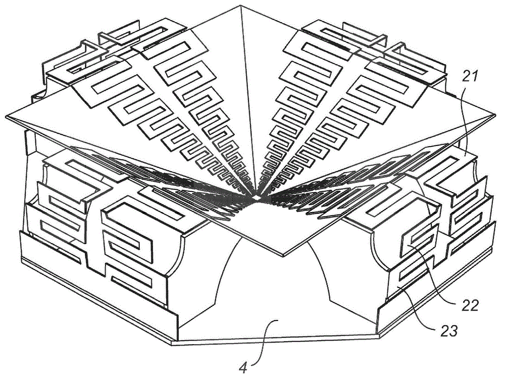
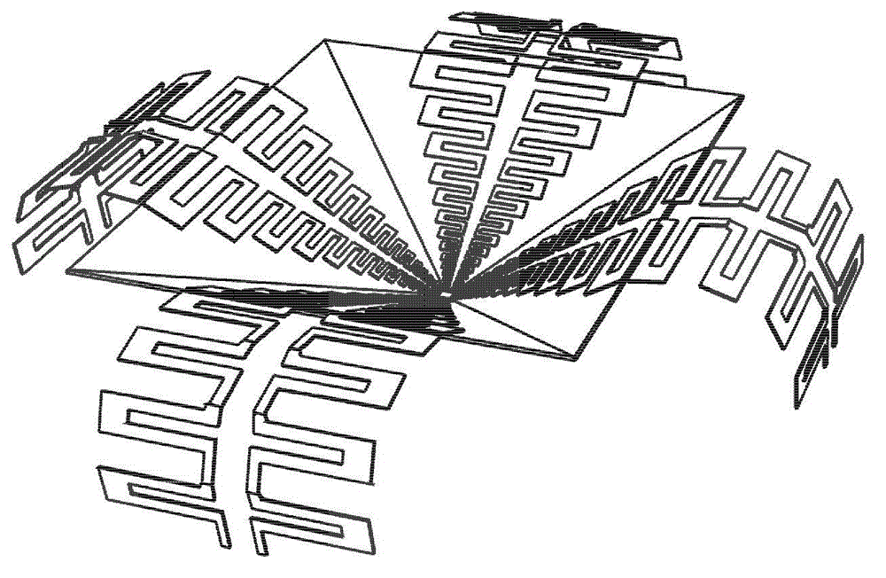
[0075] The present invention will now be described in more detail with reference to preferred embodiments. It should be understood, however, that different features in a particular embodiment can be interchanged between embodiments unless otherwise noted. Furthermore, all embodiments involve positioning the radiating dipole parts of the multi-dipole antenna in such a way that the radiation pattern results in rotational symmetry with low cross-polarization and a frequency-independent beam over a larger bandwidth width.

[0076] Dipole pairs are an essential building block of the invention. The dipole pairs are arranged above the ground plane at a predetermined separation distance.

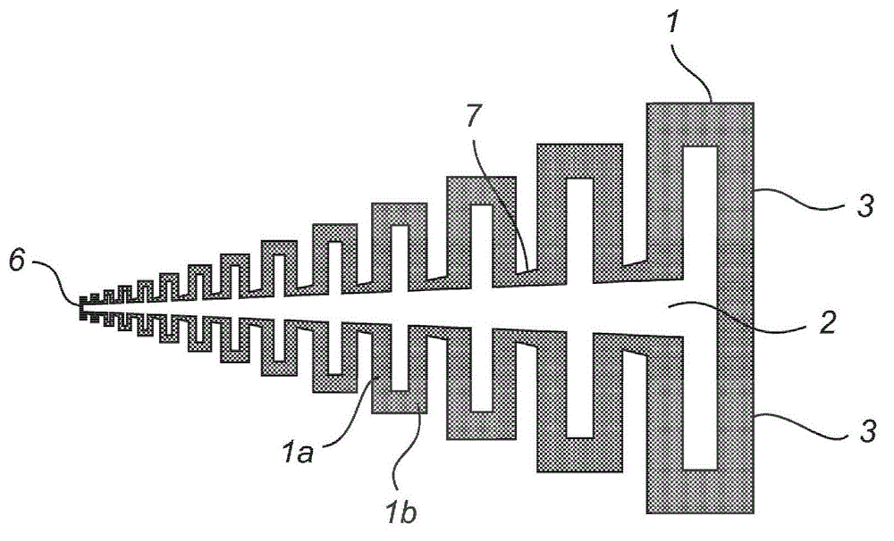
[0077] figure 1 A standard configuration of a standard 11-antenna log-periodic dipole array is shown, which is also used in embodiments of the present invention. At least two such log-periodic dipole arrays are used to form the antenna so that oppositely positioned dipoles of the same size are f...


PUM


Abstract

An improved eleven antenna is disclosed, comprising a conducting body acting as a ground plane; and at least one pair of log-periodic dipole arrays arranged above the ground plane, the dipoles of said pair of log-periodic arrays of dipoles forming dipole pairs of parallel and oppositely located dipoles of the same dimensions and arranged in such a way that the geometrical centres of each of said dipole pairs and their images in the ground plane are coinciding,wherein each dipole is a folded dipole comprising two or more parallel or nearly parallel conducting strips that are connected at one or more points or over an extended part of the conducting strips. Further, a plurality of the folded dipoles, within each of said log-periodic dipole array, being closer to said geometrical centre are extending in a first plane, and wherein the remaining at least one folded dipole being located most far away from said geometrical centre is arranged to extend in at least one additional plane, said additional plane(s) forming an angle relative to said first plane. Hereby,a more compact antenna is achieved.

Description

technical field [0001] The present invention relates to a broadband multi-dipole antenna, and in particular to an antenna having multiple frequency bands over or together covering an octave bandwidth or greater Low input reflection coefficient on , low cross polarization, rotationally symmetric beam and constant beamwidth, and constant phase center position. Background technique [0002] In general, reflector antennas have many applications, such as in point-to-point and point-to-multipoint systems for radio links, radars and radio telescopes. Modern reflector antennas are usually fed by different types of corrugated horn antennas. Their advantage is that they can provide a rotationally symmetric radiation pattern with low cross-polarization over a large frequency band compared to other feed antennas. With a proper choice of dimensions, a frequency-invariant beamwidth can also be obtained. Nonetheless, the bandwidth is usually limited to about one octave. Corrugated horn...

Claims


Application Information

Patent Timeline
IPC IPC(8): H01Q1/36H01Q1/38H01Q21/00H01Q21/24
CPCH01Q11/105H01Q19/108H01Q21/24
Inventor 派日-西蒙·基尔代尔杨健
Owner ELEVENANTENNA
Why Eureka
Try Eureka