Electric tool

A technology of electric tools and electric power, which is applied in the direction of motor tools, manufacturing tools, electric controllers, etc., can solve the problems of heavy burden and cumbersome operation of the variable speed switch, and achieve the effect of improving usability, not cumbersome trigger operation, and improving usability

Active Publication Date: 2013-06-12
MAKITA CORP
View PDF7 Cites 8 Cited by
  • Summary
  • Abstract
  • Description
  • Claims
  • Application Information

AI Technical Summary

Problems solved by technology

[0006] However, for the above-mentioned electric tools, in order to perform intermittent driving, it is necessary to frequently repeat the on and off operations of the variable speed switch.
Therefore, for the user, the operation of the shift switch is cumbersome and burdensome.

Method used


Image

  • Electric tool
  • Electric tool
  • Electric tool

Examples


Embodiment approach 1

[0036] Below, based on Figure 1 to Figure 10 , the electric power tool according to Embodiment 1 of the present invention will be described.

[0037]

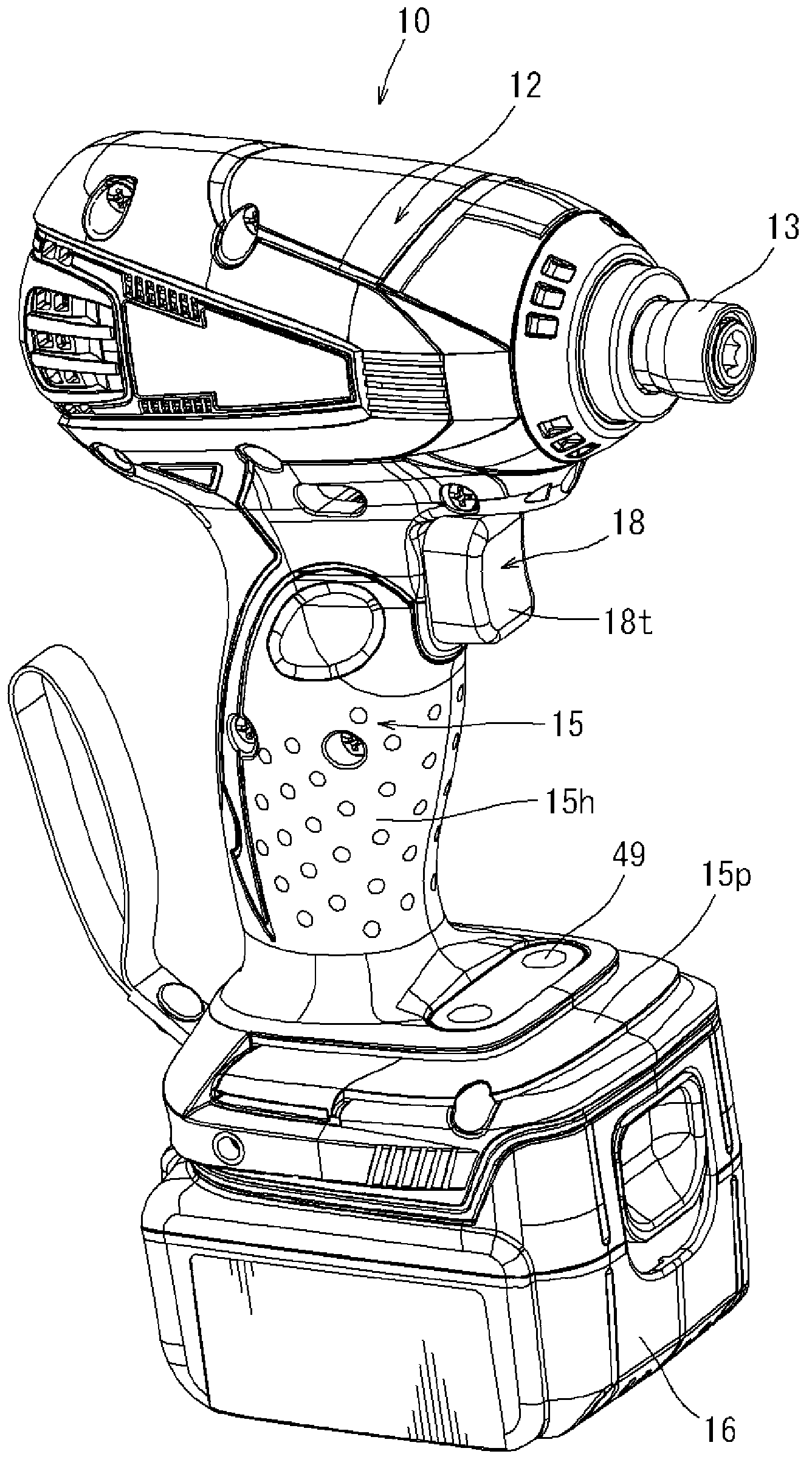
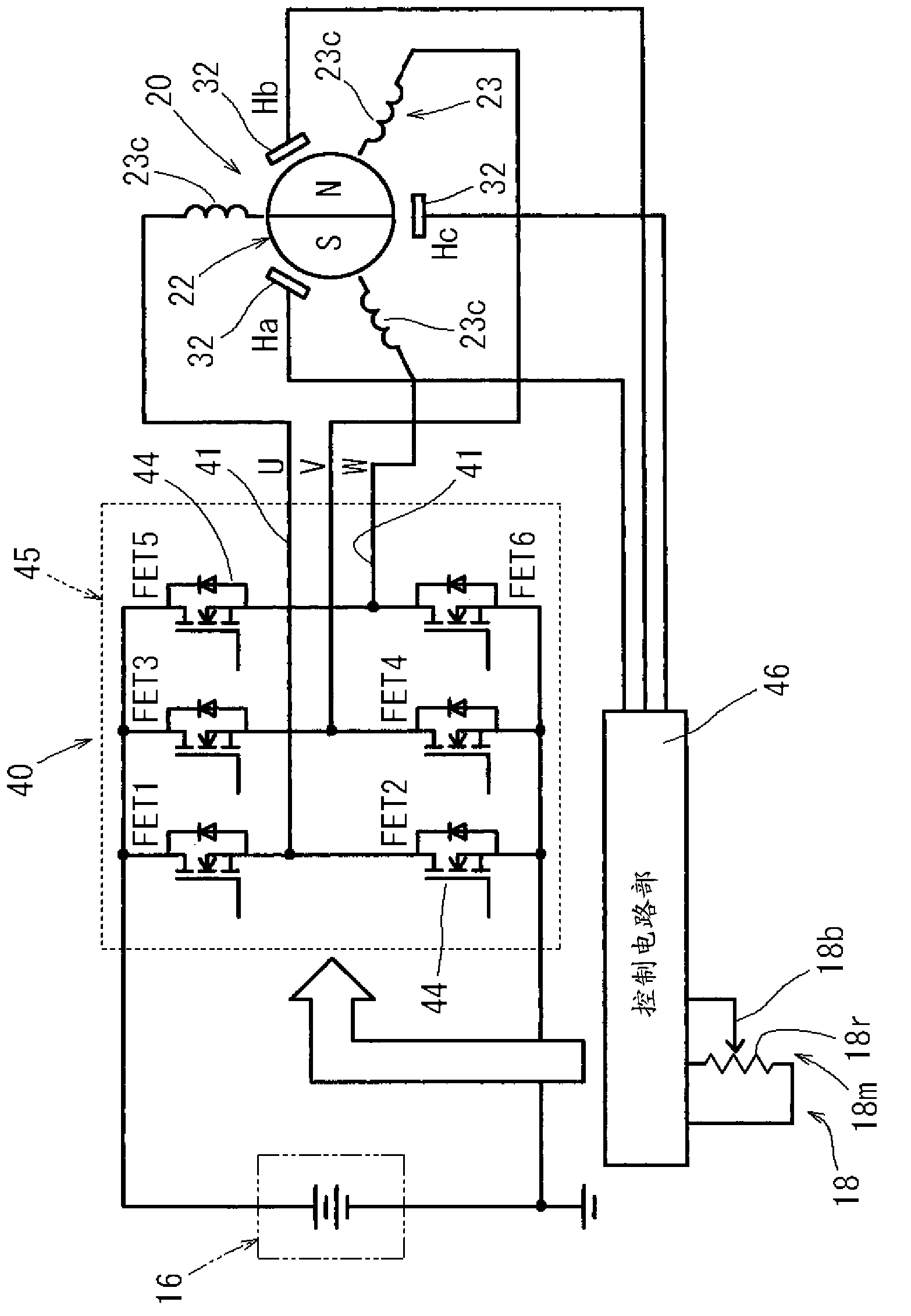
[0038] The electric tool 10 of the present embodiment is an impact drill (rotary impact tool) using a DC brushless motor 20 (hereinafter, referred to as a DC motor 20 ) as a drive source.

[0039] Such as figure 1 As shown, the electric tool 10 includes a cylindrical housing main body 12 and a handle 15 formed to protrude from a lower portion of the housing main body 12 . The handle portion 15 includes a grip portion 15h that is held by the user when using the electric power tool 10, and a battery connection portion 15p located on the lower side (front end side) of the grip portion 15h. In addition, a speed change switch 18 for a user's fingertip manipulation is provided at the base end portion of the grip portion 15h. Moreover, the connection mechanism (not shown) which connects the battery case 16 is provided in the ba...


PUM


Abstract

Disclosed is an electric tool with usability improved facilitating trigger operation of a variable speed switch of said electric tool. The disclosed electric tool is configured so as to control the amount of power supplied to a motor depending on the operation amount of the variable speed switch, and is configured to perform intermittent control, in which the amount of power supplied to the aforementioned motor is changed intermittently similarly to how ON and OFF operations of the aforementioned variable speed switch were repeated, and to perform continuous control, in which the amount of power supplied to the motor is changed continuously depending on the operation amount of the aforementioned variable speed switch.

Description

technical field [0001] The present invention relates to an electric power tool configured to control the amount of power supplied to a motor according to the amount of operation of a variable speed switch. Background technique [0002] An electric tool related thereto is described in Patent Document 1. [0003] The power tool of Patent Document 1 is a cordless impact drill using a DC motor as a drive source. The above electric tool includes a motor drive circuit composed of switching elements, and controls the voltage applied to the DC motor by pulse width modulation (PWM) according to the amount of toggle operation of the speed change switch. That is, if Figure 11 As shown in the schematic diagram of FIG. 2 , the power supply amount to the DC motor is increased or decreased in accordance with the amount of operation of the shift switch to control the rotational speed of the DC motor. [0004] Patent Document 1: Japanese Unexamined Patent Publication No. 2009-50932 [00...

Claims


Application Information

Patent Timeline
Patent Type & Authority Applications(China)
IPC IPC(8): B25F5/00B25B21/00B25B21/02
CPCB25B21/00B25B21/02B25F5/001G05B11/36H02P7/06
Inventor 铃木次郎渡边将裕
Owner MAKITA CORP
Why Eureka
Try Eureka