Non-contact angle sensor

An angle sensor, non-contact technology, applied in the direction of conversion of sensor output, instruments, and the use of electromagnetic/magnetic devices to transmit sensing components, etc., can solve problems such as the larger angle swing of the rotating shaft 10 and the poor durability of the angle sensor.

Inactive Publication Date: 2013-06-12
TOKYO COSMOS ELECTRIC CO LTD
View PDF8 Cites 10 Cited by
  • Summary
  • Abstract
  • Description
  • Claims
  • Application Information

AI Technical Summary

Problems solved by technology

Therefore, due to long-term use due to wear caused by friction between the rotating shaft 10 and the bearing, the angular swing of the rotating shaft 10 becomes large, and there is a problem of poor durability as an angle sensor.

Method used


Image

  • Non-contact angle sensor
  • Non-contact angle sensor
  • Non-contact angle sensor

Examples


Embodiment Construction

[0029] Embodiments of this invention are described by way of examples with reference to the drawings.

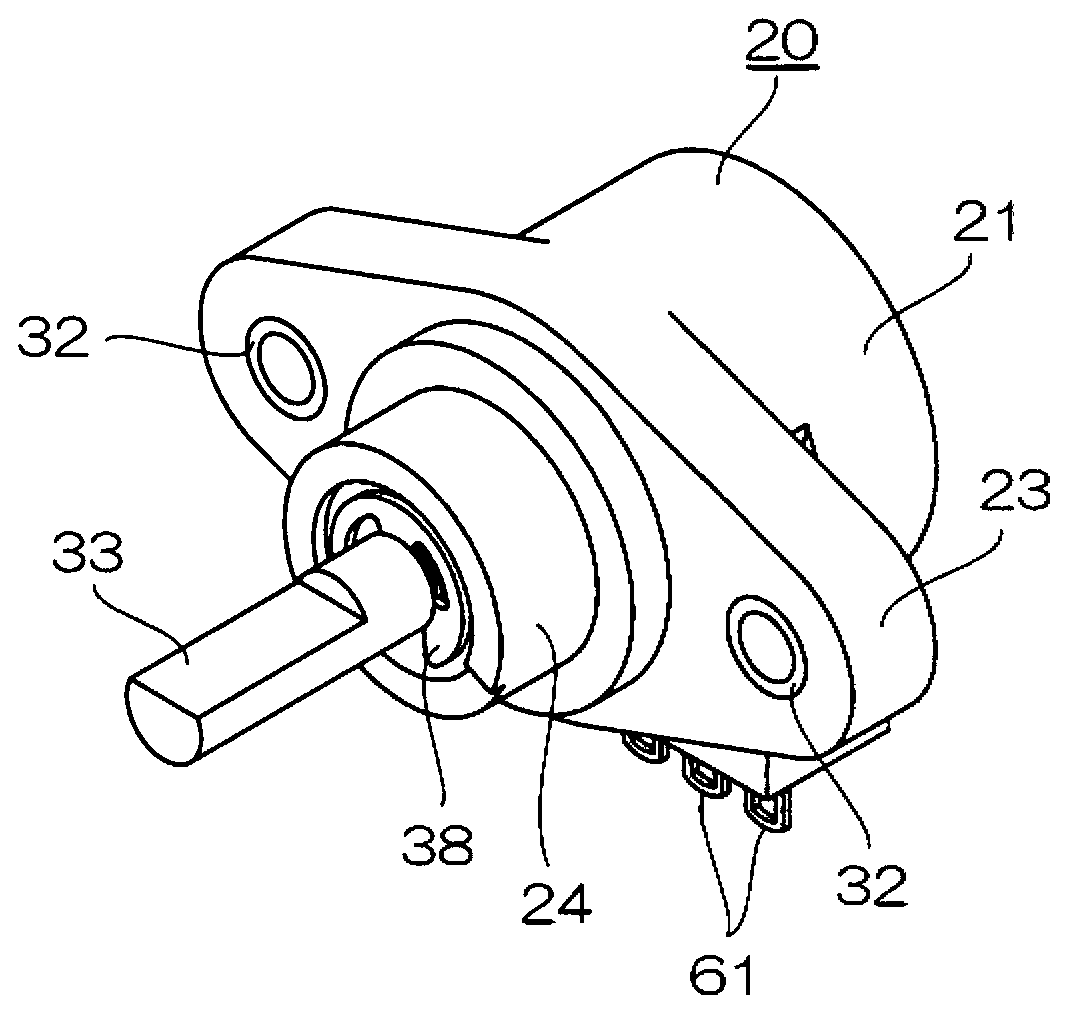
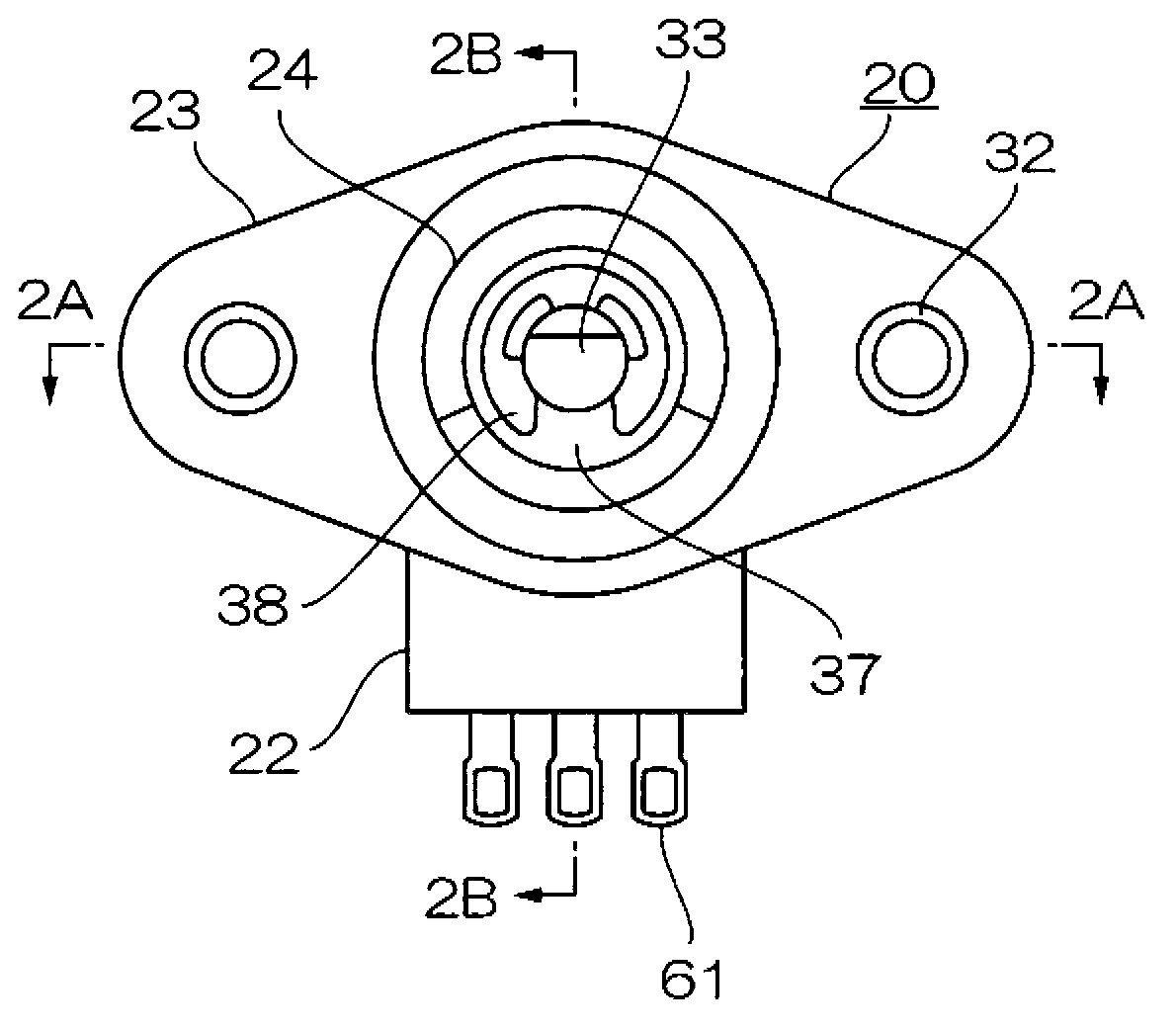
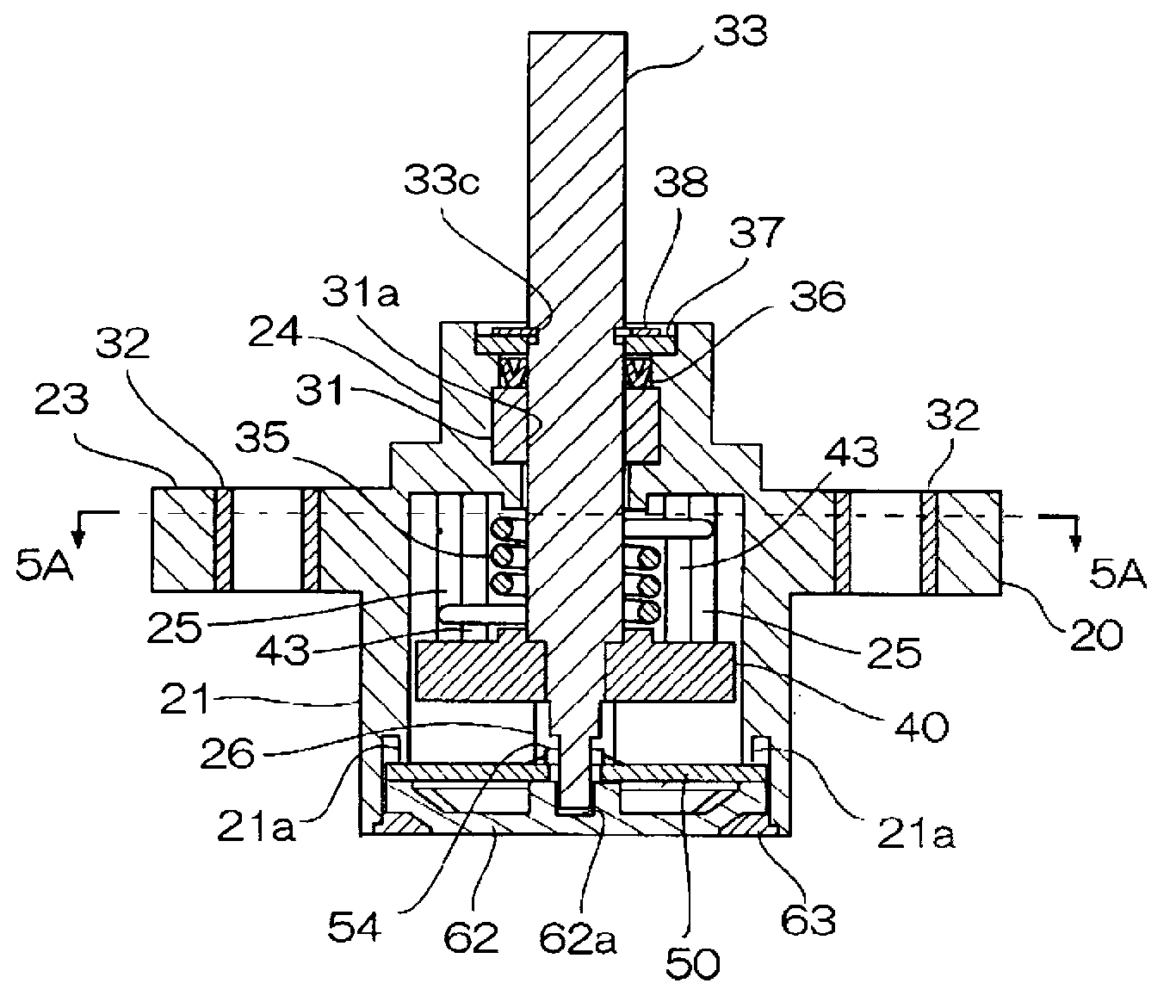
[0030] The non-contact angle sensor of this invention is a sensor that rotates a rotating shaft to output an electrical signal corresponding to a rotation angle from a neutral angle position. Figure 1A , 1B Showing the appearance of an embodiment of the non-contact angle sensor of this invention, Figure 2A express Figure 1B 2A-2A sectional view, Figure 2B express Figure 1B The structure of the 2B-2B section. in addition, image 3 It is a diagram decomposed and shown in each part.

[0031] The housing 20 has a cylindrical receiving portion 21. On the back side of the receiving portion 21, a square plate-shaped terminal lead-out portion 22 protrudes from its outer peripheral surface in a radial direction. On the front side of the receiving portion 21, a pair of mounting portions 23 protrudes greatly from the outer peripheral surface in the radial direction opposite...


PUM


Abstract

A non-contact angle sensor provided with an automatic return mechanism, configured in such a manner that a rotating shaft (33) is affixed to the center of rotation of a rotor (40) housed within a case (20), the intermediate section of the rotating shaft is inserted through and supported by an annular bearing (31), a coiled spring (35) through which the rotating shaft is inserted within the case presses the rotor relative to the case to a neutral angle position, a magnet (34) is affixed to the rear surface of the rotor so as to be separated outward in the radial direction from the rotating shaft, a magnetic sensor (53) is provided on a circuit board (50), which is provided within the case so as to face the rear surface of the rotor, so as to be separated outward in the radial direction from the rotating shaft and so as to face the magnet at an interval, and a bearing end (33b); of the rotating shaft (33) is supported by a bearing hole (62a) formed in the inner wall of a cover (62) for closing the case from behind the circuit board.

Description

technical field [0001] The present invention relates to a non-contact angle sensor provided with an automatic return mechanism of a rotating shaft, which is used for position detection of various devices. Background technique [0002] An automatic return mechanism of the rotation axis of the angle sensor is disclosed in, for example, Patent Document 1. However, the angle sensor disclosed in Patent Document 1 is a contact angle sensor that uses a slider instead of a magnet. Sliding parts have the disadvantage of easily causing bad contact due to adhesion of harmful gas, oil, and the like. [0003] As a conventional example of a non-contact angle sensor using a magnet, Figure 10 The structure of the principle of the angle sensor described in patent document 2 is shown. However, this conventional example does not have an automatic return mechanism of the rotating shaft. In this conventional example, at the rear end opposite to the driving end (front end) of the rotating shaf...

Claims


Application Information

Patent Timeline
Patent Type & Authority Applications(China)
IPC IPC(8): G01D5/12
CPCG01D5/145G01D11/245
Inventor 村上博治铃木佑二
Owner TOKYO COSMOS ELECTRIC CO LTD
Why Eureka
Try Eureka