Device of driving liquid to be nebulized by gas

A liquid atomization and gas-driven technology, which is applied in the field of medical oxygen-driven liquid atomization devices and gas-driven liquid atomization devices, can solve the problems of complex structure, increased risk of infection, and high cost.

Active Publication Date: 2013-06-19
BEIJING WANSHENG RENHE TECH
View PDF12 Cites 17 Cited by
  • Summary
  • Abstract
  • Description
  • Claims
  • Application Information

AI Technical Summary

Problems solved by technology

This scheme realizes the transition between the atomization state and the oxygen inhalation state; however, in this scheme, the oxygen delivery conduit is divided into two pipelines, the upper shunt pipe and the lower shunt pipe. The cost is increased; and when the device uses the lower shunt tube for atomization treatment, one end of the upper shunt tube is connected to the face cup and the other end is blocked by the three-way valve, and

Method used


Image

  • Device of driving liquid to be nebulized by gas
  • Device of driving liquid to be nebulized by gas
  • Device of driving liquid to be nebulized by gas

Examples


Embodiment 1

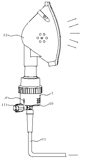
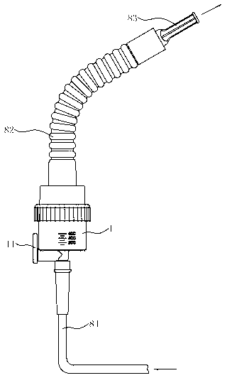
[0044] as attached figure 1 , attached figure 2 As shown, the lower part of the device is connected with a hose 84 for introducing an external air source, the gas introduced can be medical oxygen or compressed air, and the upper part of the device can be connected with a universal conversion tube 82, an oxygen inhalation atomization mask 81, a duck The mouth type contains terminal parts such as mouth 83.

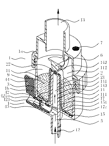
[0045] as attached image 3 As shown, the device includes a main body part 1 with an internal cavity 11, the main body part 1 can be detachably connected by upper body 1a and lower body 1b, such as threaded connection or buckle connection, the upper body 1a and lower body 1b It can be made by injection molding of one or more of polypropylene, polystyrene, acrylonitrile-butadiene-styrene and other materials. The inner cavity 11 of the main body part 1 includes a liquid storage chamber 111 capable of storing a certain amount of liquid 9 and an atomization chamber 112 above...

Embodiment 2

[0053] Such as Figure 6As shown, the second air outlet 3 is located on the bottom 15 of the lower body 1b of the main body part 1. The second air outlet 3 can communicate the air inlet chamber 5 with the inner cavity 11 of the main body part 1, and its ventilation area is larger than that of the first air outlet. A ventilation area of ​​the air outlet 142 . The second air outlet 3 extends to the inner cavity 11 of the main body part 1 to form a second air outlet extension part 31 of hollow structure, and its top 311 plane is higher than the liquid level of the liquid 9 stored in the liquid storage chamber 111, and a resistance is provided on it. The liquid cover 10 is tightly connected with the second gas outlet extension part 31 , which can prevent the atomized particles in the atomization chamber 112 from falling into the second gas outlet extension part 31 . The second air outlet 3 is closed or unblocked by a component that is convenient for manual operation and can move ...

Embodiment 3

[0057] Such as Figure 8 As shown, the second air outlet 3 is located on the bottom 15 of the lower body 1b of the main body part 1. The second air outlet 3 can communicate the air inlet chamber 5 with the inner cavity 11 of the main body part 1, and its ventilation area is larger than that of the first air outlet. The ventilation area of ​​the air outlet. The second air outlet 3 extends to the inner cavity 11 of the main body part 1 to form a second air outlet extension part 31 of hollow structure, and its top 311 plane is higher than the liquid level of the liquid 9 stored in the liquid storage chamber 111, and a resistance is provided on it. The liquid cover 10 is snap-connected with the second air outlet extension 31 to prevent the atomized particles in the atomization chamber 112 from falling into the second air outlet extension 31 . The second air outlet 3 is closed or unblocked by a component that is convenient for manual operation and can move in spatial position due ...


PUM


Abstract

In allusion to the fact that currently patient who needs nebulizer therapy also needs oxygen therapy at the same time clinically, a more smooth oxygen conveying device needs to be rapidly used to carry out oxygen therapy after nebulization is finished, and frequent device replacement can apparently increase nursing burden and hospitalization costs. The device of driving liquid to be nebulized by gas can achieve complete and rapid switch between a nebulization state and an oxygen uptake state. A second air outlet is formed in the device, and a sealing part is arranged on the device. When the patient needs the oxygen therapy, sealing to the second air outlet is relieved by adjusting the sealing part, oxygen can go out smoothly, and the patient can receive the oxygen therapy. When the patient needs the nebulizer therapy, the second air outlet is sealed by adjusting the sealing part, liquid medicine in the device is nebulized, and the patient can receive the nebulizer therapy. The device of driving the liquid to be nebulized by the gas not only reduces workload of medical workers, but also meets requirements of safe and rapid switch between the nebulization state and the oxygen uptake state clinically.

Description

technical field [0001] The invention relates to a gas-driven liquid atomization device, in particular to a medical oxygen-driven medicinal liquid atomization device, which can quickly switch between the atomization state and the oxygen inhalation state, and belongs to the field of medical equipment. Background technique [0002] Oxygen inhalation therapy and liquid drug nebulization inhalation therapy are commonly used treatment methods in clinical medicine. As far as atomization is concerned, the liquid medicine is transformed into small droplets with a diameter of about 5 microns through physical action, and the mist is inhaled into the patient's respiratory tract to facilitate For treatment, ultrasonic nebulizers were the most common a few years ago, but their disadvantages are that they are not easy to clean and need to be connected to a power source. In recent years, passive devices that use high-pressure gas, especially medical oxygen with a large background pressure, t...

Claims


Application Information

Patent Timeline
IPC IPC(8): A61M11/00A61M16/00
Inventor 董东生徐晓明张月梅马晓敏
Owner BEIJING WANSHENG RENHE TECH
Why Eureka
Try Eureka