
air delivery system

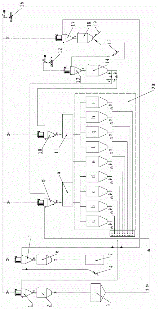
A technology of air conveying and feeding, which is used in conveyors, conveying bulk materials, transportation and packaging, etc. It can solve the problems of large investment and achieve the effect of simple operation, high automation and high degree of integration.

Active Publication Date: 2015-10-28
JIANGSU PURESTAR EP TECH CO LTD
View PDF8 Cites 0 Cited by
  • Summary
  • Abstract
  • Description
  • Claims
  • Application Information

AI Technical Summary

Problems solved by technology

Then, there are several kinds of devices that work independently. If there is secondary feeding in production, another same device needs to be installed, so the investment is relatively large.

Method used


Image

  • air delivery system

Examples


Embodiment Construction

[0023] The air delivery system of the present invention will be further described in detail below in conjunction with the drawings and embodiments. The following examples are used to illustrate the present invention, but are not intended to limit the scope of the present invention.

[0024] In the description of the present invention, it should be noted that the terms "center", "longitudinal", "transverse", "upper", "lower", "front", "rear", "left", "right", " The orientations or positional relationships indicated by "vertical", "horizontal", "top", "bottom", "inner", "outer", etc. are based on the orientation or positional relationships shown in the drawings, and are only for the convenience of describing the present invention and simplifying Describes, but does not indicate or imply that the device or element referred to must have a specific orientation, be constructed in a specific orientation, and operate in a specific orientation, and therefore should not be construed as ...


PUM


Abstract

The invention relates to the field of material handling, in particular to a fully enclosed pneumatic conveying system with a high automaticity, and the pneumatic conveying system is suitable for a continuous production, and includes a fan, and a plurality of transit bunkers which are respectively connected with the fan through pipelines. A feeding port and a discharging port are formed in the transit bunker, wherein the feeding port is connected with material drainage ports of multiple feeding devices through the pipelines, and the discharging port is communicated with a material charging port of a material handling device. In the process of conveying material, the material cannot fall to the ground and be interrupted, and the operation is simple. The pneumatic conveying system is a fully enclosed system, and no dust flies in the transportation process; meanwhile a dust removal system can suck the partial dust produced in a blanking link and cannot affect workshops and staff. In addition, the automaticity degree and integration degree of the system are high, and the system is simple in operation, too much manual control is unnecessary, and no staff fatigue phenomenon appears.

Description

technical field [0001] The invention relates to the field of material conveying, and is a fully enclosed and highly automated airflow conveying system suitable for continuous production. Background technique [0002] The existing methods of material transmission in the workshop mainly include bucket elevators, conveyor belts, and screw conveying systems. These methods all have common defects. First of all, in daily work, it can be found that these systems are not completely closed. Of course, such a device is more practical for some dust-free materials, and it is not practical if used in some dusty workshops in some production. If it is used in a dusty workshop or in the production of small granular raw materials, on the one hand, it is easy to cause harm to the human body, and on the other hand, it will also cause the material to slip, which is not conducive to production. Secondly, the operation of these types of equipment requires manpower, such as the front feeding sect...

Claims


Application Information

Patent Timeline
Patent Type & Authority Patents(China)
IPC IPC(8): B65G53/28B65G53/36B65G53/40B65G53/34
Inventor 王洪炳
Owner JIANGSU PURESTAR EP TECH CO LTD
Learn More