Unitary plastic conductivity sensor

A conductivity sensor, plastic technology, applied in the direction of material electrochemical variables, material resistance, fluid resistance measurement, etc., can solve problems such as cost leakage

Active Publication Date: 2013-06-19
ROSEMOUNT INC
View PDF6 Cites 6 Cited by
  • Summary
  • Abstract
  • Description
  • Claims
  • Application Information

AI Technical Summary

Problems solved by technology

Traditional manufacturing methods have created problems inc...

Method used


Image

  • Unitary plastic conductivity sensor
  • Unitary plastic conductivity sensor
  • Unitary plastic conductivity sensor

Examples


Embodiment Construction

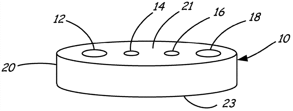
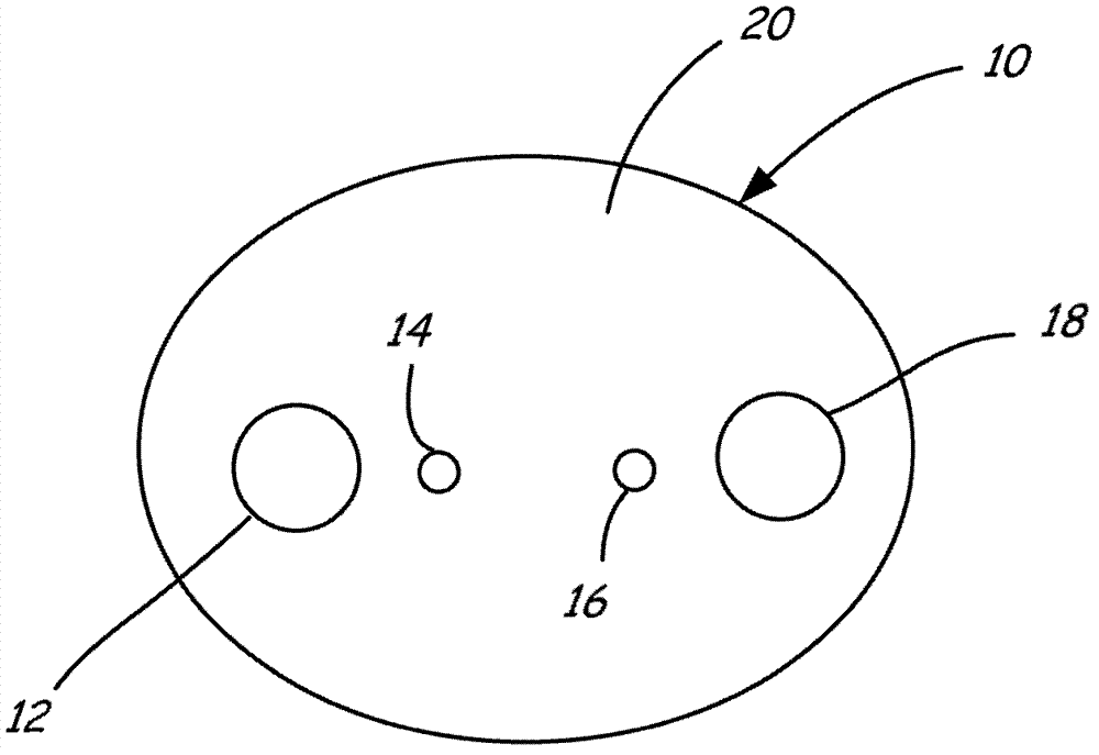
[0014] figure 2 and 3 are perspective and top views of a monolithic plastic conductivity sensor 10 according to an embodiment of the invention. As used herein, "plastic" is intended to mean a synthetic organic polymer that, while soft, can be molded into shape and then set into a rigid or slightly elastic form. Sensor 10 includes at least two and preferably four conductive electrodes 12 , 14 , 16 , 18 disposed within an insulating sensor body 20 . The illustrated sensor body has a pair of opposing faces 21, 23 and a side wall 25 extending therebetween. Each of the conductive electrodes 12 , 14 , 16 , 18 extends from the first face 21 through the sensor body 20 to the second face 23 . In use, the faces 21, 23 will be in direct contact with the sample solution to determine the conductivity of the sample solution. like image 3 As shown, when four electrodes are used, they are preferably collinear with each other.

[0015] The entire conductivity sensor 10 is considered mo...


PUM


Abstract

A contacting-type conductivity sensor (10) includes an electrically-insulative plastic body (20) and a plurality of electrodes (12, 14, 16, 18). The plurality of conductive electrodes (12, 14, 16, 18) is disposed in the plastic body (20). Each electrode (12, 14, 16, 18) is constructed of plastic and fused with the electrically-insulative plastic body (20). A method of manufacturing the conductivity sensor is provided along with a single-use bioreactor (50) employing the sensor (10).

Description

technical field [0001] Liquid conductivity measurement systems are used to measure the conductivity of water and aqueous or non-aqueous solutions in environmental, medical, industrial and other applications where an indication of the ionic content of the liquid is required. Background technique [0002] Liquid conductivity was measured in each case to provide a parameter that may be related to bulk ionic concentration. In cases where a single type of ion is present, the conductivity may actually be related to the specific ion concentration. Even in the presence of several different ionic compounds, the measurement of the bulk conductivity of a liquid can still provide very useful information. Accordingly, conductivity measurements have been widely adopted and utilized by industry for a variety of different purposes. [0003] Typically, a contact conductivity measurement system includes a conductivity cell and an associated conductivity meter. figure 1 Such a system is ill...

Claims


Application Information

Patent Timeline
IPC IPC(8): G01R27/22
CPCG01N27/30G01N27/07
Inventor 冯昌东巴里·W·本顿
Owner ROSEMOUNT INC
Why Eureka
Try Eureka