An ion receiving device for ion mobility spectrometry

An ion mobility spectrometry and ion receiving technology, which is applied to the parts of the particle separator tube, can solve the problems of affecting the ion receiving efficiency, affecting the sensitivity of the instrument, etc., and achieve the effect of preventing discharge phenomenon, simple structure and high receiving efficiency.

Active Publication Date: 2015-11-04
DALIAN INST OF CHEM PHYSICS CHINESE ACAD OF SCI
View PDF5 Cites 0 Cited by
  • Summary
  • Abstract
  • Description
  • Claims
  • Application Information

AI Technical Summary

Problems solved by technology

Does the design of the Faraday disk structure determine the distribution of the electric field, which affects the receiving efficiency of ions to a large extent, thus affecting the sensitivity of the instrument

Method used


Image

  • An ion receiving device for ion mobility spectrometry

Examples


Embodiment

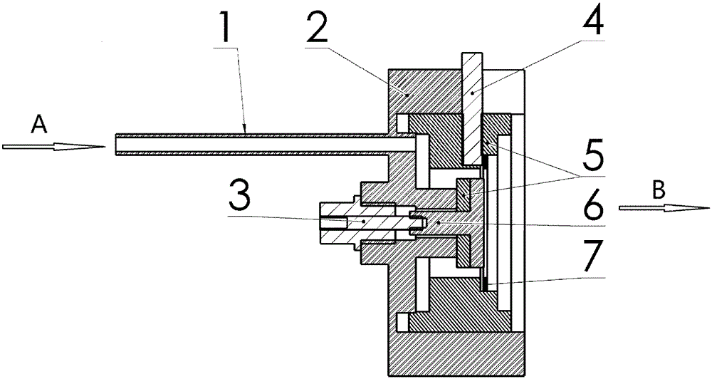
[0011] An ion receiving device for ion mobility spectrometry, comprising a Faraday disk 6 and a shielding cylinder 2, the shielding cylinder 2 is a metal cylinder with one end open and the other end closed, and the closed end of the metal cylinder is provided with an air inlet pipe 1 and a signal line lead out The outer side of the signal line lead-out hole is provided with a signal lead-out joint 3, and the inside of the signal line lead-out hole is provided with a Faraday disk 6. The Faraday disk 6 is placed in the metal cylinder and connected with the signal lead-out joint 3; the ion receiving surface of the Faraday disk 6 is connected to the The axis of the metal cylinder is vertical, and the receiving surface faces the opening end of the metal cylinder; the Faraday disk 6 and the metal cylinder are insulated by an insulating pad, and a grid 7 is arranged in front of the receiving surface of the Faraday disk 6, and a gap is left between the grid 7 and the receiving surface. ...


PUM


Abstract

The invention discloses a novel ion receiving device based on the operating principle of a faraday disk. The ion receiving device can effectively receive ions in gas phase and is used for converting IMS ion signals to current signals. The ion receiving device for the IMS has the advantages of being simple in structure, reliable in functions, and capable of effectively preventing electric discharge phenomena near the faraday disc from happening.

Description

technical field [0001] The device of the invention belongs to ion mobility spectrometry technology. The device is a new type of ion receiving device. Based on the working principle of the Faraday disk, it can efficiently receive ions in the gas phase, and convert ion signals into current signals for ion mobility spectrometry. It has the advantages of simple structure and reliable function, and can effectively prevent the occurrence of discharge near the Faraday disk. Background technique [0002] Ion mobility spectrometry is a technique for material analysis based on the determination of the migration characteristics of ions in the gas phase in an electric field. The device used is called an ion transfer tube (Drift Tube). Most of the current transfer tubes use Faraday disks as ion receiving devices. The design of the Faraday disk structure determines the distribution of the electric field, which affects the receiving efficiency of ions to a large extent, thus affecting ...

Claims


Application Information

Patent Timeline
Patent Type & Authority Patents(China)
IPC IPC(8): H01J49/02
Inventor 李海洋杜永斋陈创周庆华王卫国
Owner DALIAN INST OF CHEM PHYSICS CHINESE ACAD OF SCI
Why Eureka
Try Eureka