
Ultraviolet light emitting device

A technology of light-emitting devices and light-emitting structures, applied in semiconductor devices, electric solid-state devices, electrical components, etc., can solve the problems of reducing light extraction efficiency and disappearing

Active Publication Date: 2013-06-19
SUZHOU LEKIN SEMICON CO LTD
View PDF6 Cites 6 Cited by
  • Summary
  • Abstract
  • Description
  • Claims
  • Application Information

AI Technical Summary

Problems solved by technology

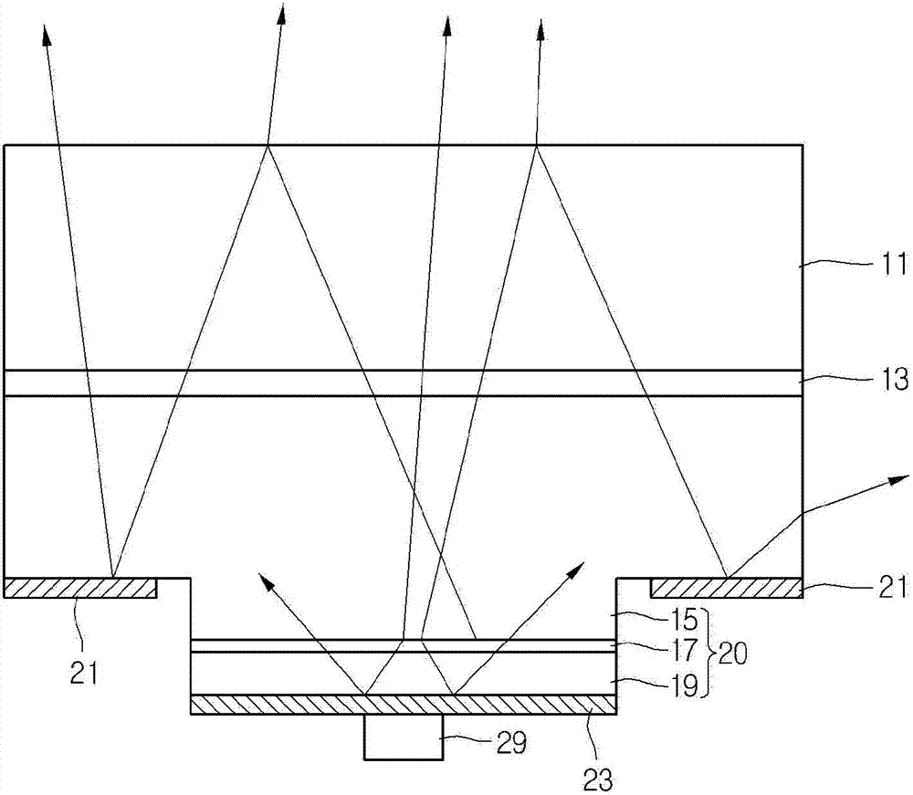
[0006] Although ultraviolet light is output from the ultraviolet light emitting device, a larger amount of ultraviolet light is not output to the outside but is absorbed or disappears in the ultraviolet light emitting device
Therefore, the light extraction efficiency may be reduced

Method used


Image

  • Ultraviolet light emitting device
  • Ultraviolet light emitting device
  • Ultraviolet light emitting device

Examples


Embodiment Construction

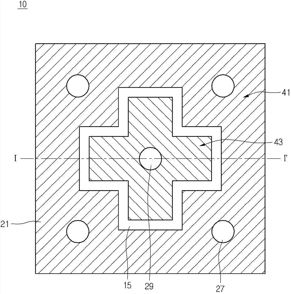
[0019] In the description of the following embodiments, it will be understood that when a layer (or film), region, pattern or structure is referred to as being on another substrate, another layer (or film), another region, another pad or another When a pattern is "on" or "under" it may be "directly" or "indirectly" on another substrate, layer (or film), region, pad or pattern, or one or more intervening layers may also be present. Such positions of layers have been described with reference to the drawings.

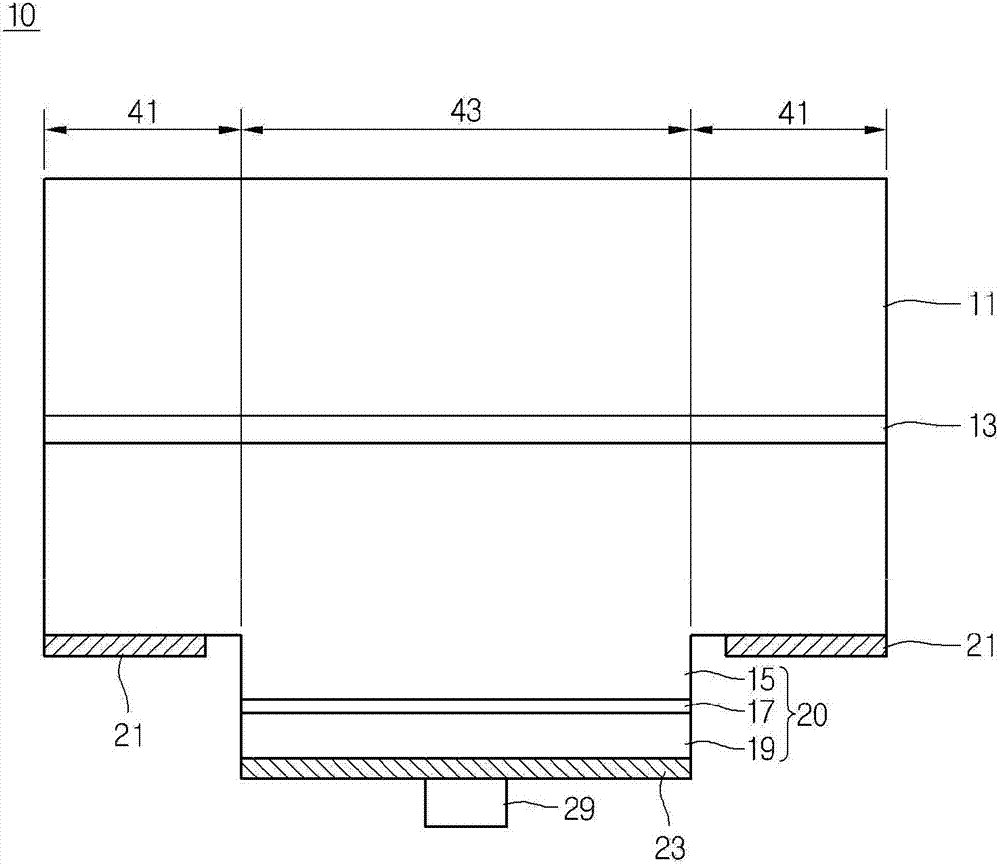
[0020] Hereinafter, the embodiments will be described with reference to the drawings. The thickness and size of each layer shown in the drawings may be exaggerated, omitted, or schematically drawn for the purpose of convenience or clarity. Also, the size of elements does not utterly reflect an actual size.

[0021] Although the following description is made in that the ultraviolet light-emitting device is limited to a flip-chip type ultraviolet light-emitting device incl...


PUM


Abstract

The ultraviolet light emitting device includes a substrate; a light emitting structure on the substrate, and including a plurality of compound semiconductors, each including at least a first conductive semiconductor layer, an active layer, and a second conductive semiconductor layer; a first electrode layer on the first conductive semiconductor layer; and a second electrode layer on the second conductive semiconductor layer. The first electrode layer is spaced apart from a side surface of the active layer, and is provided along a peripheral portion of the active layer. At least one of the first and second electrode layers is a reflective layer.

Description

[0001] Pursuant to 35 U.S.C. §119(a), this application claims Korean Patent Application No. 10-2011-0134019 filed on December 13, 2011 and Korean Patent Application No. 10-2012- filed on November 5, 2012 0124003, the entire contents of which are incorporated herein by reference. technical field [0002] Embodiments relate to light emitting devices. Background technique [0003] Light emitting diodes (LEDs) are semiconductor light emitting devices that convert electrical current into light. [0004] Since semiconductor light emitting devices can obtain light with high luminance, semiconductor light emitting devices have been widely used as light sources for displays, vehicles, or lighting devices. [0005] Recently, ultraviolet light emitting devices capable of outputting ultraviolet light have been proposed. [0006] Although ultraviolet light is output from the ultraviolet light emitting device, a larger amount of ultraviolet light is not output to the outside but is abso...

Claims


Application Information

Patent Timeline
Patent Type & Authority Applications(China)
IPC IPC(8): H01L33/40H01L33/38
CPCH01L33/20H01L33/38H01L33/405H01L2924/181H01L2224/48091H01L2224/48247H01L2224/48257H01L2924/00012H01L2924/00014H01L33/36H01L33/60
Inventor 洪二朗崔云庆
Owner SUZHOU LEKIN SEMICON CO LTD
Learn More