Electric storage device and method for manufacturing the same

a technology of storage devices and collector electrodes, which is applied in the manufacture of final products, sustainable manufacturing/processing, electrochemical generators, etc., can solve the problems of reducing the strength of collector electrodes, difficult to achieve multi-layer configuration, unstable positioning between electrodes and separators, etc., and achieves easy miniaturization, high heat resistance, and easy configuration

Inactive Publication Date: 2014-12-11
MURATA MFG CO LTD
View PDF3 Cites 1 Cited by
  • Summary
  • Abstract
  • Description
  • Claims
  • Application Information

AI Technical Summary

Benefits of technology

[0015]According to the present invention as described thus far, an electric storage device having a high heat resistance, in which multiple lay...

Problems solved by technology

However, the conventional technique described above has a problem in that because the electrodes and separators are not integrated by joining the electrodes and the separator to be affixed, the positioning between the electrodes and the separators is unstable, which makes it difficult to achieve a multilayer configuration.
There is a further problem in that thinning the collector electrode to achieve smaller sizes also reduces the strength of...

Method used


Image

  • Electric storage device and method for manufacturing the same
  • Electric storage device and method for manufacturing the same
  • Electric storage device and method for manufacturing the same

Examples


first example

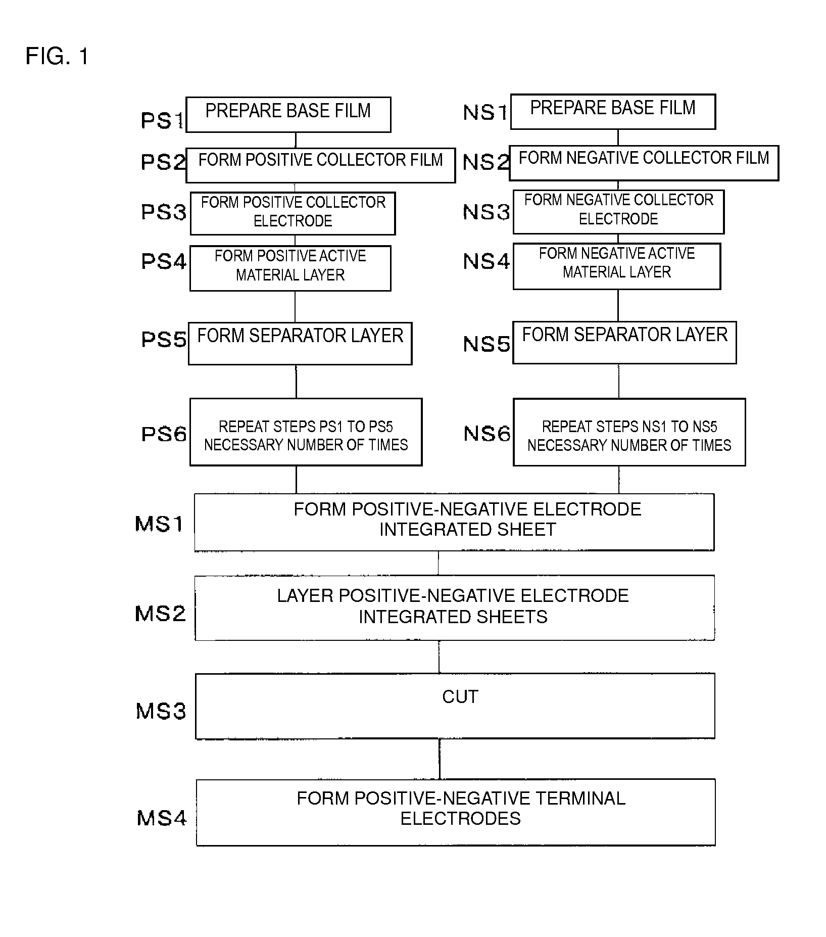
[0164]In a first example, the electric double-layer capacitor was manufactured according to the manufacturing method described in the aforementioned embodiment. Note that an electrostatic capacity value was set to 480 mF by design.

[0165]Creation of Samples

[0166]Sample No. 1

[0167]First, a base PEN film on which a silicone-based mold releasing layer 101 was formed was prepared as the base film 100. A joining layer slurry, produced by dissolving a siloxane-modified polyimide precursor (30 wt %) in methyl proxitol acetate (70 wt %), was gravure-printed onto this surface and then dried for 30 seconds at 100° C., forming the joining resin layer 121 at a thickness of 2 μm.

[0168]Next, a 500 nm-thick Al film was formed on the surface of the joining resin layer 121 through vacuum deposition as the positive collector film 102. The deposition conditions for the aluminum film were a degree of vacuum of 3×10⁻⁴ Pa, a current value of 800 mA, a deposition rate of 30 Å / sec, and a base cooling temper...

second example

[0240]In a second example, the electric double-layer capacitor was manufactured according to the manufacturing method described in the aforementioned embodiment. However, when joining the two positive-negative electrode integrated sheets 50A to each other, the temperature of the pressure plate was set to 130° C., the pressure used in the pressurization was set to 5 MPa, and the pressurizing time was set to 10 seconds.

[0241]Creation of Samples

[0242]Sample No. 10

[0243]Aside from the temperature of the pressure plate being set to 130° C., the pressure used in the pressurization being set to 5 MPa, and the pressurizing time being set to 10 seconds when joining the two positive-negative electrode integrated sheets 50A to each other, an electric double-layer capacitor of Sample No. 10 was obtained in the same manner as with Sample No. 1.

[0244]Sample No. 11

[0245]Aside from the temperature of the pressure plate being set to 130° C., the pressure used in the pressurization being set to 5 MPa...


PUM


Abstract

An electric storage device having a multilayer body in which a separator layer is provided between a positive or negative first electrode and a second electrode of the opposite polarity to the first electrode, an electrolyte, and a package that holds the multilayer body and the electrolyte, and includes at least two first-polarity compound sheets, each configured by integrating a first-polarity collector electrode, a first-polarity active material layer provided on one main surface of the first-polarity collector electrode, and a separator layer that covers at least part of the one main surface. Another main surface of the first-polarity collector electrode in one of the at least two first-polarity compound sheets and another main surface of the first-polarity collector electrode in another of the first-polarity compound sheets are opposed to each other and joined via a joining layer. The joining layer contains a high-polymer having imide coupling in its main chain.

Description

CROSS REFERENCE TO RELATED APPLICATIONS[0001]The present application is a continuation of International application No. PCT / JP2012 / 081473, filed Dec. 5, 2012, which claims priority to Japanese Patent Application No. 2011-286120, filed Dec. 27, 2011, the entire contents of each of which are incorporated herein by reference.FIELD OF THE INVENTION[0002]The present invention relates to electric storage devices and methods for manufacturing the electric storage devices.BACKGROUND OF THE INVENTION[0003]Electric storage devices such as electric double-layer capacitors are widely being used as small, lightweight batteries capable of achieving comparatively high capacities.[0004]Such electric storage devices are manufactured by first forming an electrode by applying a polarizing electrode layer to both surfaces of a collector electrode configured of aluminum foil and then layering the electrodes with separators therebetween, as disclosed in Patent Document 1, for example.[0005]Patent Documen...

Claims


Application Information

Patent Timeline
IPC IPC(8): H01G11/68H01G11/70H01G11/84H01M4/02H01M4/04
CPCH01G11/68H01G11/70H01G11/84H01G11/10H01G11/66H01G11/72H01M10/0463H01M10/052H01G11/52Y02E60/10Y02P70/50H01G11/86H01G11/82Y02E60/13
Inventor HORIKAWA, KEIJI
Owner MURATA MFG CO LTD
Why Eureka
Try Eureka