
Retarder for transport equipment

A transportation and retarder technology, applied in the field of parts and components, can solve the problems of large size of the retarder, limited scope of use, high cost, etc., to reduce the volume, reduce the possibility of risk, and reduce the original cost. Effect

Inactive Publication Date: 2013-06-19
TELMA AUTOMOBILE BRAKING SYST SHANGHAI
View PDF8 Cites 2 Cited by
  • Summary
  • Abstract
  • Description
  • Claims
  • Application Information

AI Technical Summary

Problems solved by technology

[0005] The retarder used in the prior art is very expensive due to its large size and heavy weight, so its application range is greatly limited

Method used


Image

  • Retarder for transport equipment
  • Retarder for transport equipment
  • Retarder for transport equipment

Examples


Embodiment Construction

[0018] A vehicle retarder for transportation equipment according to a specific embodiment of the present invention will be described in detail below with reference to the accompanying drawings. However, the present invention should be understood as not limited to such embodiments described below, and the technical idea of ​​the present invention can be implemented in combination with other known technologies or other technologies having the same functions as those known technologies.

[0019] In the following description, in order to clearly show the structure and working method of the present invention, many directional words will be used to describe, but "front", "rear", "left", "right", "outer", "inner" should be used ", "outward", "inward", "axial", "radial" and other terms are to be understood as convenient terms, and should not be understood as limiting terms. In addition, the word "inside" used in the following description mainly refers to the side close to the transmis...


PUM


Abstract

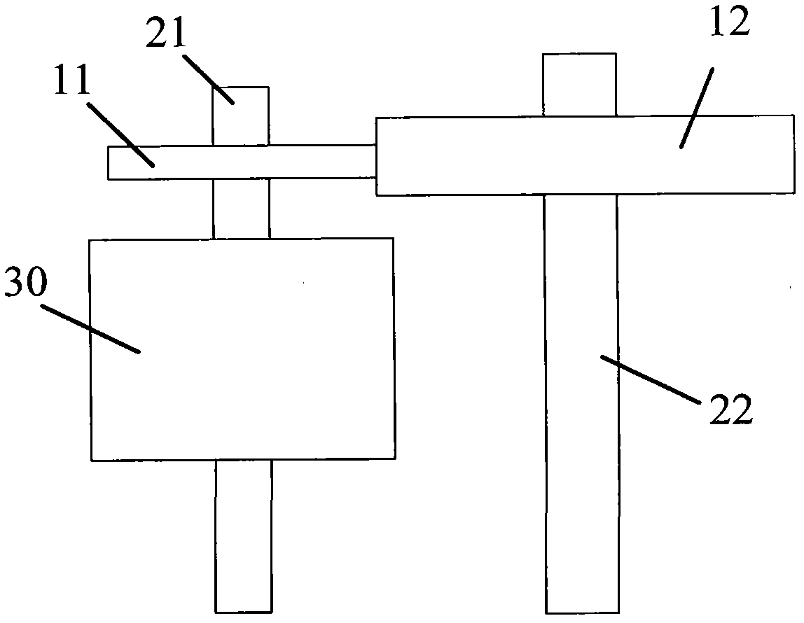
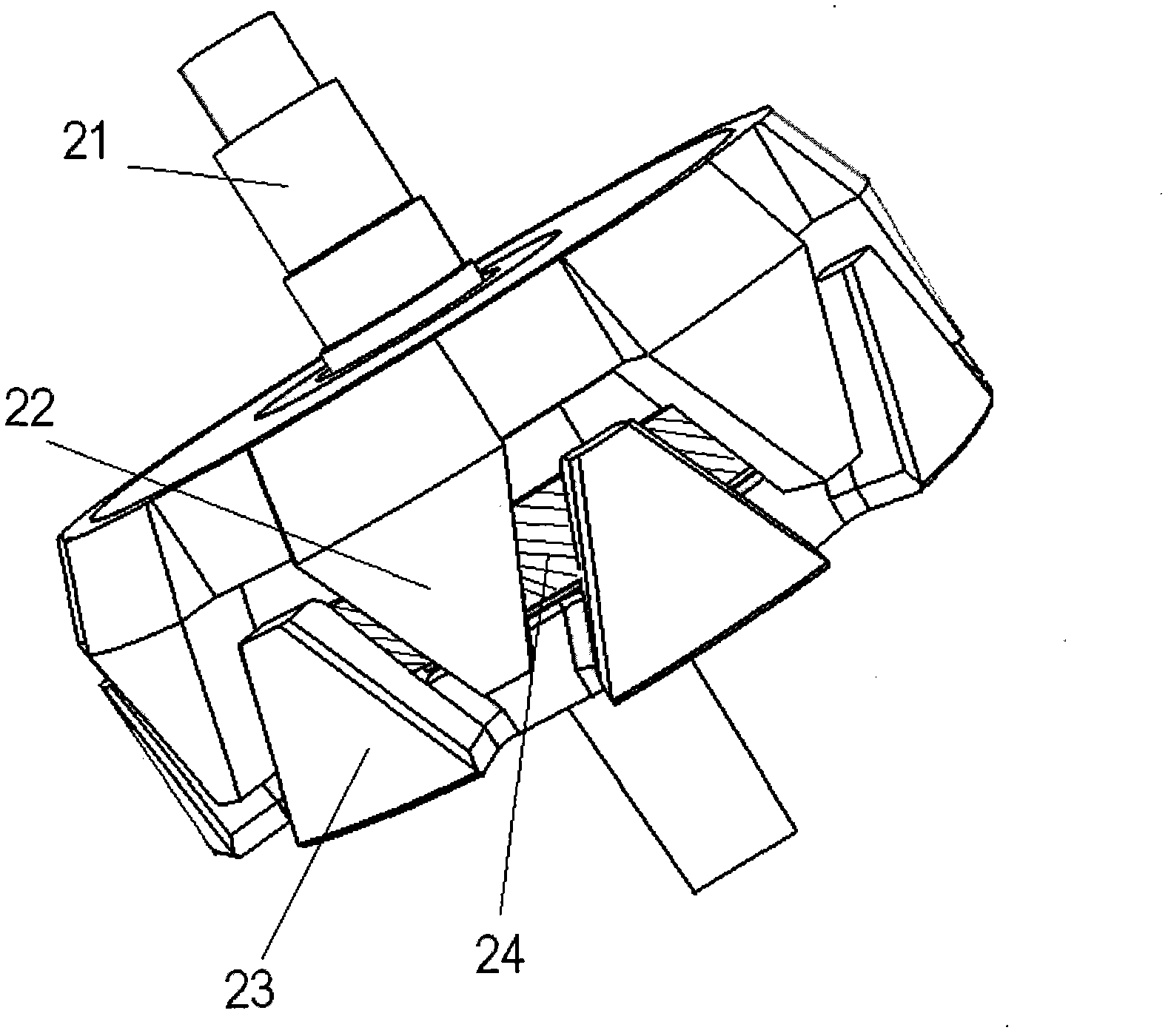
The invention provides a retarder for transport equipment. The retarder for the transport equipment comprises a retarder transmission shaft, a first stator, and a first rotor which is placed outside the first stator. The retarder transmission shaft is in coupling with a transmission shaft of the transport equipment through a gear unit.

Description

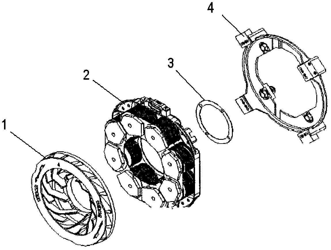
technical field [0001] The invention relates to a component used for transportation equipment, in particular to a retarder used for large-scale transportation equipment. Background technique [0002] The eddy current retarder is an auxiliary braking device for automobiles. The device is installed between the car drive axle and the gearbox, and realizes non-contact braking through the principle of electromagnetic induction. The eddy current retarder can provide a strong braking torque in a fairly wide speed range, thereby avoiding safety hazards such as vehicle deviation, traditional brake failure and tire blowout, so it is widely used in motor vehicles, especially large machines on the train. [0003] Such as figure 1 as shown in figure 1 It is a relatively typical eddy current retarder in the prior art. The eddy current retarder is composed of a rotor 1 , a stator assembly 2 , a rotor adjusting gasket 3 and a support frame 4 . The stator assembly 2 usually consists of...

Claims


Application Information

Patent Timeline
Patent Type & Authority Applications(China)
IPC IPC(8): H02K7/116H02K16/00
Inventor 刘增岗
Owner TELMA AUTOMOBILE BRAKING SYST SHANGHAI
Learn More