

Crankshaft mirror
A crankshaft milling machine, X-axis technology, applied in milling machine equipment, milling machine equipment details, metal processing equipment and other directions, can solve the problem of hindering the swinging movement of the swinging head 105, and achieve the effect of smooth and stable swinging movement
- Summary
- Abstract
- Description
- Claims
- Application Information
AI Technical Summary
Problems solved by technology
Method used
Image

Examples
no. 1 approach
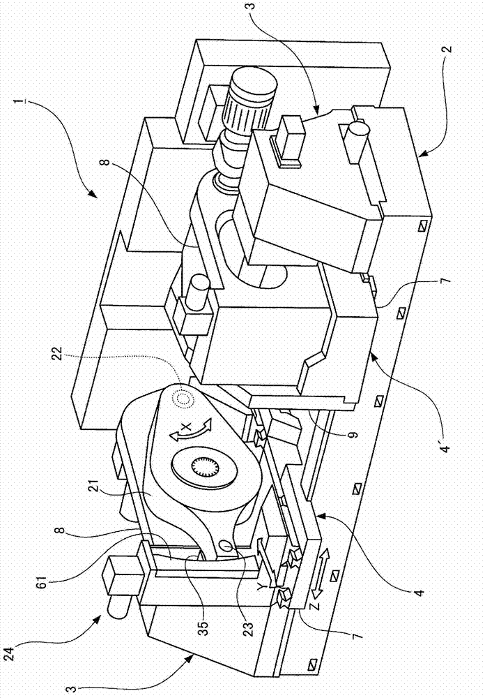
[0051] figure 1 >
[0052] figure 1The shown crankshaft milling machine 1 is provided with: a bed 2 constituting a base as the base of the main body; 3 between two tool units 4, 4'.
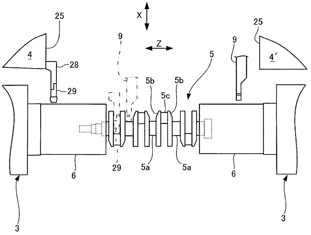
[0053] figure 2 >
[0054] Such as figure 2 As shown, chucks 6 for clamping a workpiece (crankshaft) 5 are disposed on opposing surfaces of the workpiece seats 3, 3, respectively.
[0055] figure 2 >
[0056] The workpiece 5 is, for example, a crankshaft used in a 4-cylinder engine. The workpiece 5 has desired spindle necks 5 a arranged at predetermined intervals in the direction along the horizontal axis. A pin journal portion 5c is formed between the adjacent main journal sections 5a via a weight portion 5b.
[0057] Figure 1~3 >
[0058] Such as figure 1 As shown, each tool unit 4, 4' is equipped with a workpiece 5 to be processed (refer to figure 2 ) is movably arranged on the saddle 7 on the bed 2 in the Z-axis direction parallel to the horizontal axis.
[0059] Such as ...
PUM
 Abstract
Description
Claims
Application Information