Method for monitoring a brake system and brake system

A technology of brake equipment and brake-by-wire, which is applied in the direction of brake action starting devices, brakes, brake components, etc., and can solve problems that have not been described in detail

Active Publication Date: 2013-06-19
CONTINENTAL AUTOMOTIVE TECH GMBH
View PDF8 Cites 23 Cited by
  • Summary
  • Abstract
  • Description
  • Claims
  • Application Information

AI Technical Summary

Problems solved by technology

In this application there is no detailed description of h

Method used


Image

  • Method for monitoring a brake system and brake system
  • Method for monitoring a brake system and brake system

Examples


Embodiment Construction

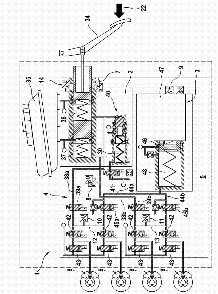
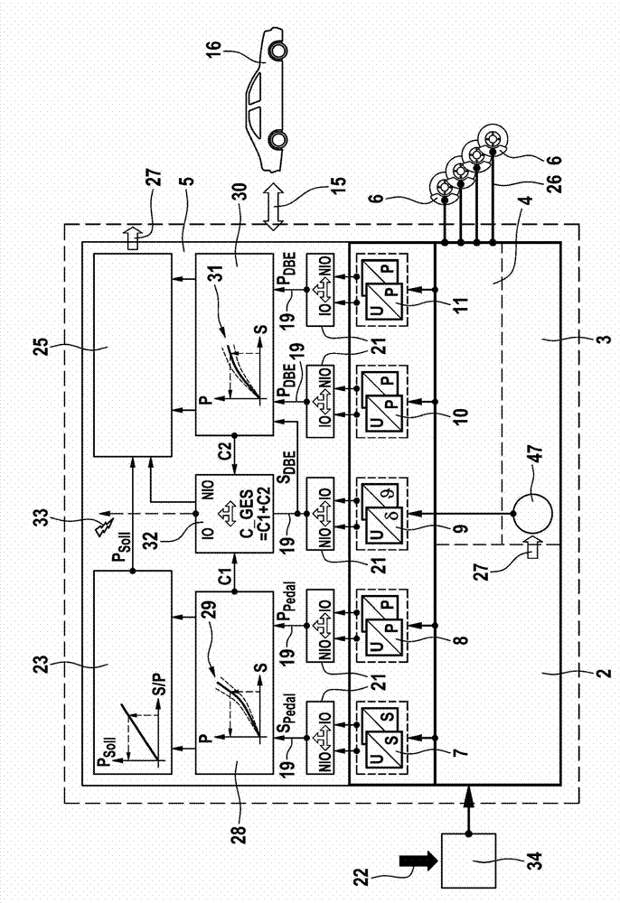
[0022] figure 1 An exemplary braking system is schematically shown in . The system 1 comprises an operating device 2 , an electromechanical operating unit 3 , a hydraulic wheel brake pressure modulation device 4 (HCU: hydraulic control unit) and an electronic control and regulating unit 5 (ECU: electronic control unit), which can be controlled by means of For actuation or brake pedal 34 is actuated by the driver of the vehicle (driver braking request 22 ), the electromechanical actuating unit is an electrically controllable pressure supply device 3 , which is connected to the output of the wheel brake pressure modulation device To which wheel brakes 6 are connected, the electronic control and regulation unit is used to control and / or test components of the brake system.

[0023] The actuating device 2 includes a dual-circuit brake master cylinder or tandem master cylinder with two hydraulic pistons arranged one behind the other, which delimit hydraulic chambers or pressure ch...


PUM


Abstract

The invention relates to a method for monitoring a brake system for motor vehicles, which can be actuated both by a vehicle driver and independently of the vehicle driver in what is known as a ''brake-by-wire'' mode, comprising a hydraulic actuation device (2) which can be actuated by means of a brake pedal (34) and has a main brake cylinder, to which wheel brakes (6) are connected, in particular in at least two brake circuits (12, 13), a simulation device (40), which comprises at least one elastic element (30) and gives the vehicle driver a comfortable pedal feeling, an electrically controllable pressure-providing device (3), which is formed by a cylinder/piston assembly, the piston (46) of which can be actuated by an electromagnetic actuator (47), wherein a first measurement variable (PDBE) characterising the pressure of the pressure-providing device (3) is detected, and an electronic control unit (5), wherein a second measurement variable (SDBE) characterising a position of the piston (46) is detected, and wherein the detected measurement values of the first and second measurement variables (SDBE, PDBE) are compared (30) to a predetermined characteristic map (31) of the first and second measurement variables in order to monitor a functional status of the brake system.

Description

technical field [0001] The invention relates to a method for monitoring a brake system according to the preamble of claim 1 and a brake system according to the preamble of claim 10 . Background technique [0002] In motor vehicle technology, "brake-by-wire" braking systems are becoming more and more popular. Such a brake system usually comprises, in addition to a master brake cylinder actuatable by the vehicle driver, an electrically controllable pressure supply device, by means of which in the "brake-by-wire" operating mode the wheel brakes or Operation of the master brake cylinder. In order to convey a suitable pedal feel to the driver of the vehicle in the "brake-by-wire" operating mode, the brake system usually includes a brake pedal feel simulator. In such a braking system, the wheel brakes can also be actuated on the basis of electronic signals without active assistance from the driver of the vehicle. Such an electronic signal can be output, for example, by an elect...

Claims


Application Information

Patent Timeline
IPC IPC(8): B60T8/40B60T8/88
CPCB60T7/042B60T8/4081B60T8/885B60T13/662B60T17/22B60T2270/404B60T2270/406B60T2270/413B60T7/06B60T8/40B60T8/88B60T13/12B60T17/221
Inventor J·容贝克S·林肯巴赫S·A·德鲁姆M·贝西尔J·库尔巴萨J·菲雷尔
Owner CONTINENTAL AUTOMOTIVE TECH GMBH
Why Eureka
Try Eureka