Electro-pneumatic brake control device

a control device and electropneumatic technology, applied in the direction of braking systems, process and machine control, instruments, etc., can solve the problems of limited number of possible braking operations using the service brake, and the inability of the compressed air generating compressor to deliver compressed air to the compressed air reservoir tank

Active Publication Date: 2014-02-18
ZF CV SYST EURO BV
View PDF10 Cites 12 Cited by
  • Summary
  • Abstract
  • Description
  • Claims
  • Application Information

AI Technical Summary

Benefits of technology

[0006]The electro-pneumatic brake control device according to embodiments of the present invention enables a vehicle to be braked slowly and parked safely even in the event of the failure of the on board power supply, especially the electric power supply of the brake control device, and the associated failure of an electro-pneumatically actuated parking brake. This is advantageous, in particular, since the vehicle engine also fails in the event of power supply failure. As a result, a compressed air generating compressor can no longer deliver compressed air for the compressed air brakes to the compressed air reservoir tank. This means that the remaining number of possible braking operations using the service brake is limited. It is, therefore, important that the vehicle be brought safely into a parked position in the event of the failure of the electric power supply.
[0007]By virtue of the present invention, the brake control device can be brought into an operating condition in which the compressed air line leading to the spring store part of the spring brake cylinder is vented in throttled manner in the event of failure of the electric power supply when valve devices are deenergized. Because of the throttled venting of the spring store part, the parking brake is applied slowly and the vehicle is braked slowly. This benefits traffic safety as following traffic is not endangered by an emergency braking operation.
[0010]Preferably, the air flow boosting valve device is designed as a relay valve, wherein the relay piston has an aperture that places the outlet of the relay valve in communication with its control input in throttled manner. This aperture in the relay piston is provided as an orifice or bore. It offers the advantage that an orifice provided on the throttled venting device can be configured with a definite minimum size. Specifically, the control volume of such a relay valve is usually very small and, so, it vents very rapidly. However, rapid venting may lead to abrupt braking. In order to avoid rapid venting, an orifice on the corresponding venting device would, therefore, have to be of very small size. However, this can lead to problems. Especially in the case of fouling or icing, the danger exists that venting may no longer take place properly. Because of the aperture provided in the relay piston of the relay valve in this preferred embodiment of the present invention, the working volume of the relay valve is slowly reduced via the aperture in the relay piston and, thus, also via the throttled venting device. The control volume of the relay valve therefore appears to be virtually increased. As a result, the orifice provided on the throttled venting device can be configured with a larger cross section, and, as a result, stopping up or clogging of the venting device due to fouling, icing, etc. is prevented.
[0011]It is thus an object of the present invention to provide an electro-pneumatic brake control device for a vehicle parking brake control system that enables the vehicle to be braked slowly and parked safely even in the event of failure of the electric power supply and the associated failure of the electro-pneumatically actuated parking brake.

Problems solved by technology

As a result, a compressed air generating compressor can no longer deliver compressed air for the compressed air brakes to the compressed air reservoir tank.
This means that the remaining number of possible braking operations using the service brake is limited.

Method used


Image

  • Electro-pneumatic brake control device
  • Electro-pneumatic brake control device
  • Electro-pneumatic brake control device

Examples


Embodiment Construction

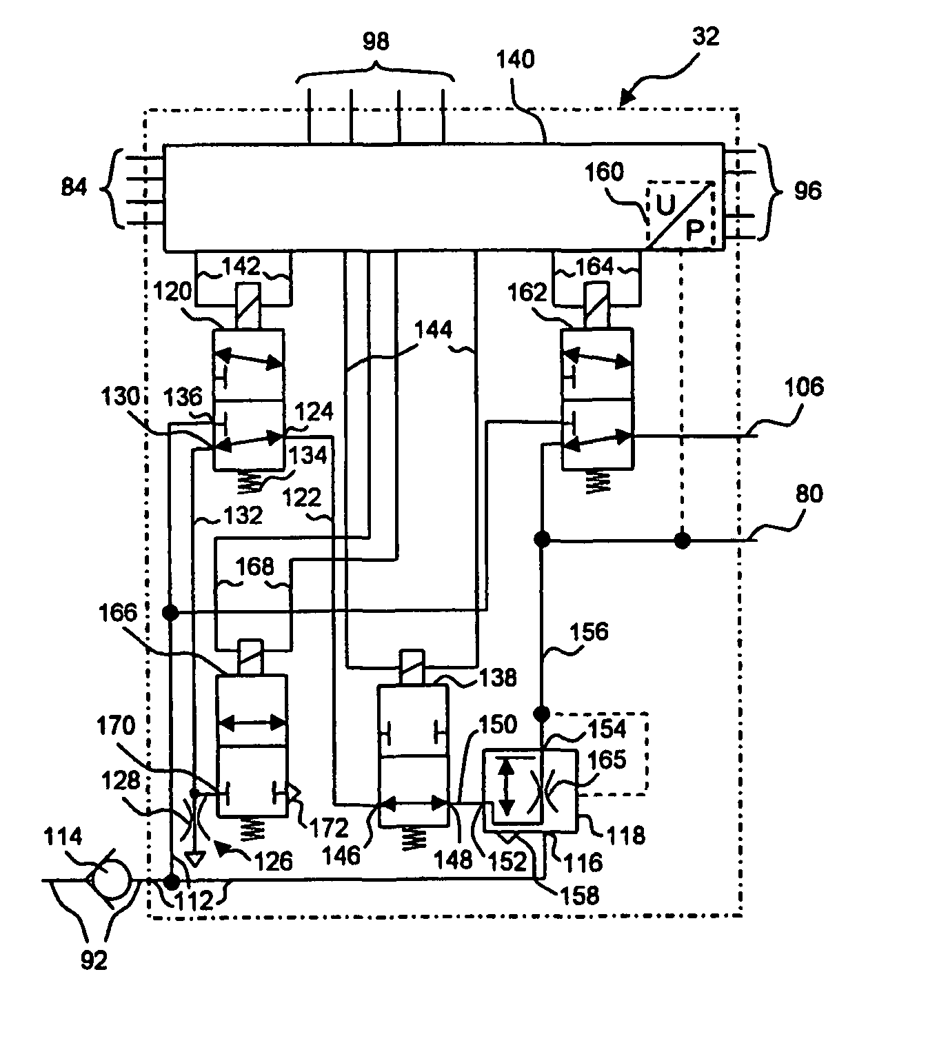
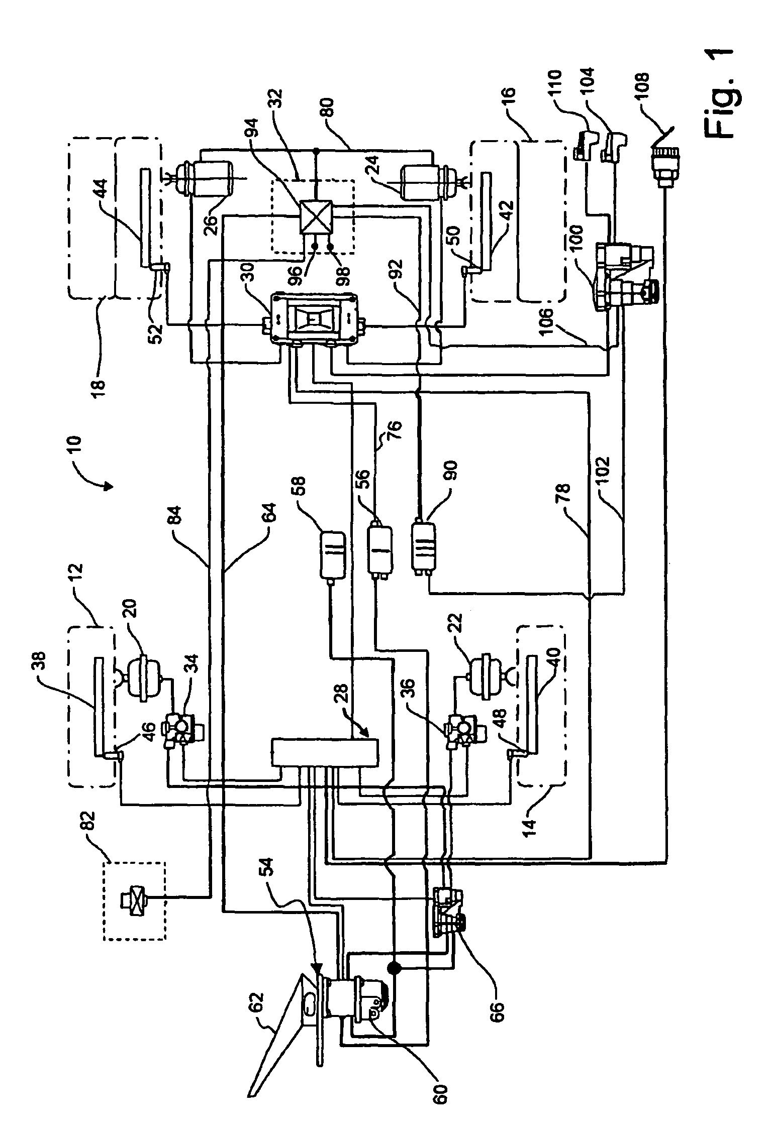
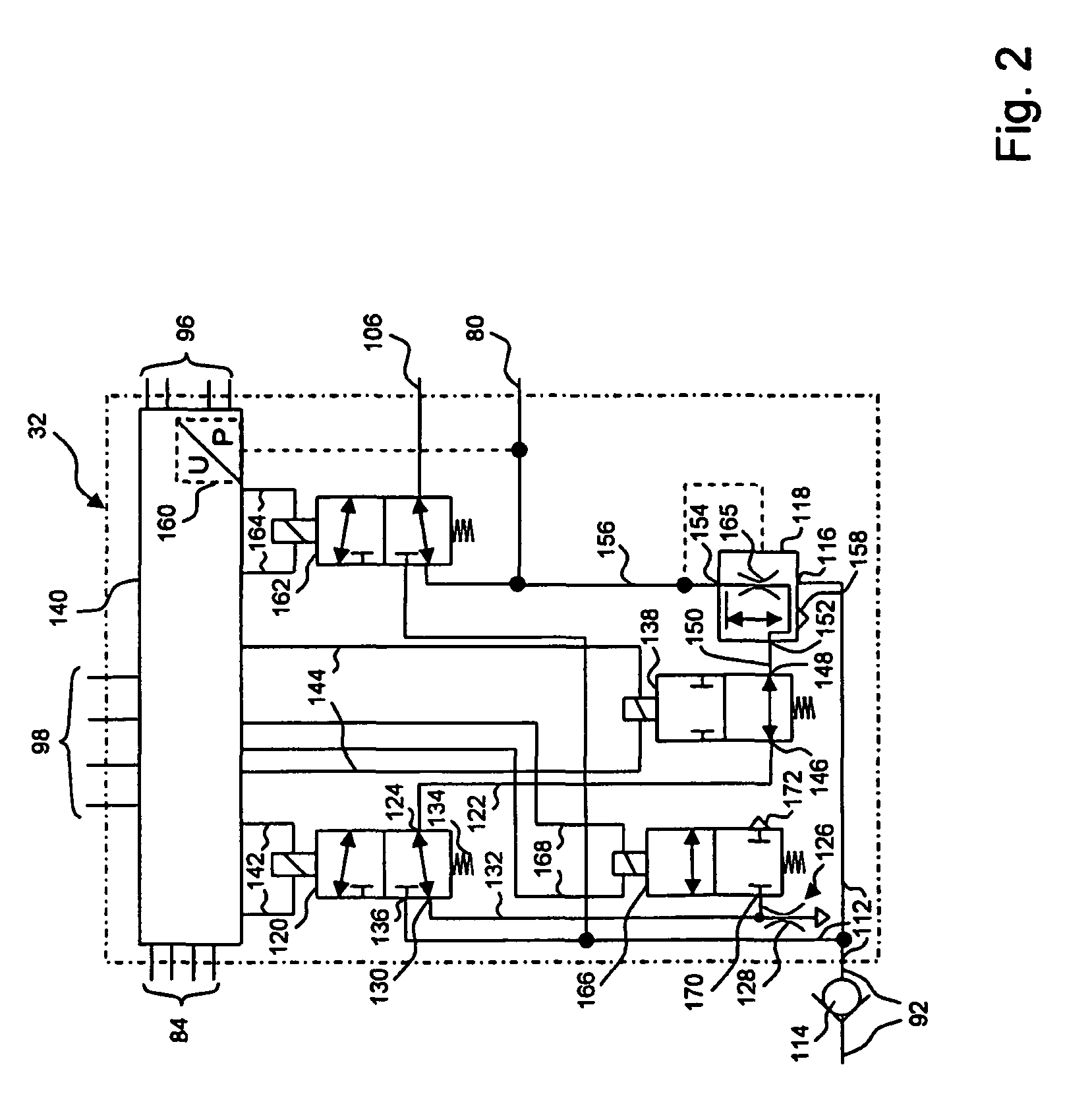
[0017]Referring now to FIG. 1, a vehicle compressed air brake system will first be discussed in general terms in order to set the stage for a detailed discussion of the inventive electro-pneumatic device for controlling a parking brake integrated into such a compressed air brake system. FIG. 1 schematically shows a compressed air brake system 10 for a vehicle having four wheels 12, 14, 16, 18. Brake system 10 is electrically controlled, meaning that the injection of brake pressure to brake cylinders 20, 22, 24, 26 of wheels 12, 14, 16, 18 is controlled by electric and electronic control elements. Brake cylinders 20, 22 of front wheels 12, 14 are controlled by a front axle brake control module 28, and brake cylinders 24, 26 of rear wheels 16, 18 are controlled by a rear axle brake control module 30. Brake cylinders 24, 26 of rear wheels 16, 18 are designed as combined service and spring brake cylinders, wherein the spring store parts are controlled by an electro-pneumatic brake contr...


PUM


Abstract

An electro-pneumatic brake control device is provided for controlling the parking brake of a vehicle having compressed-air-actuated brake cylinders, at least one of which is a spring brake cylinder with a spring store part. Valve devices place the brake control device into various operating states. In a first operating state, the valve devices are at least partially supplied with current and switched such that a compressed air line to the spring store part of the spring brake cylinder is aerated. In a second state, the valve devices are at least partially supplied with current and switched such that the compressed air line is deaerated. In a third state, which can be activated in the event of failure of the electrical energy supply of the brake control device, the valve devices are switched to a currentless state such that the compressed air line is automatically deaerated in throttled manner.

Description

FIELD OF THE INVENTION[0001]The present invention relates generally to an improved electro-pneumatic brake control device for controlling the parking brake of a vehicle.BACKGROUND OF THE INVENTION[0002]EP 1 571 061 A1 describes a brake control device and brake system of the general type under consideration. Such systems provide a service brake, which can be actuated by means of a brake pedal, and a parking brake (often also referred to as a handbrake), which can be actuated by means of an electric signal transducer.[0003]The failure of the electric power supply can be a problematic event in such electrically controlled brake systems, as electric components, such as electric control systems and electrically actuated solenoid valves, can no longer be actuated. Furthermore, electric signal transducers for the parking brake also can fail as a result of such power failures. DE 199 53 805 C1 therefore proposed that emergency braking be initiated automatically by venting a spring actuator ...

Claims


Application Information

Patent Timeline
Patent Type & Authority Patents(United States)
IPC IPC(8): B60T8/32
CPCB60T13/683B60T8/327B60T8/32
Inventor BENSCH, UWEFORSTER, HENNINGKIEL, BERND-JOACHIMMENZE, WILFRIEDROSENDAHL, HARTMUTSTRUWE, OTMAR
Owner ZF CV SYST EURO BV
Why Eureka
Try Eureka