Quenching sensor and quenching method for shaft parts

A technology for quenching inductors and shaft parts, applied in the direction of quenching devices, furnace types, furnaces, etc., can solve the problems of reducing the reliability of threaded connections against shock and vibration, unstable quality of laser beam quenching surfaces, and uneven distribution of magnetic lines of force, etc. , to achieve the effect of reducing proximity effect, low requirements for equipment and other hardware conditions, and low manufacturing cost

Inactive Publication Date: 2015-10-07
CHINA NORTH IND NEW TECH PROMOTION INST +1
View PDF9 Cites 1 Cited by
  • Summary
  • Abstract
  • Description
  • Claims
  • Application Information

AI Technical Summary

Problems solved by technology

[0003] Among the existing quenching methods, the laser quenching method easily leads to unstable quality of the quenched surface of the parts due to the uneven density of the laser beam; the overall quenching of shaft parts tends to reduce the reliability of threaded connections and shock resistance
[0004] The commonly used high-frequency induction heating and quenching method results in uneven distribution of magnetic force lines at the quenched part on the shaft part due to the limitation of the shape of the inductor, and the formed quenching surface is too far away from the right-angle point of the shaft neck, and the quenching effect is poor.

Method used


Image

  • Quenching sensor and quenching method for shaft parts
  • Quenching sensor and quenching method for shaft parts
  • Quenching sensor and quenching method for shaft parts

Examples


Embodiment Construction

[0043] The technical solutions of the present invention will be further described below in conjunction with the accompanying drawings and through specific implementation methods.

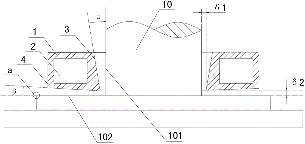
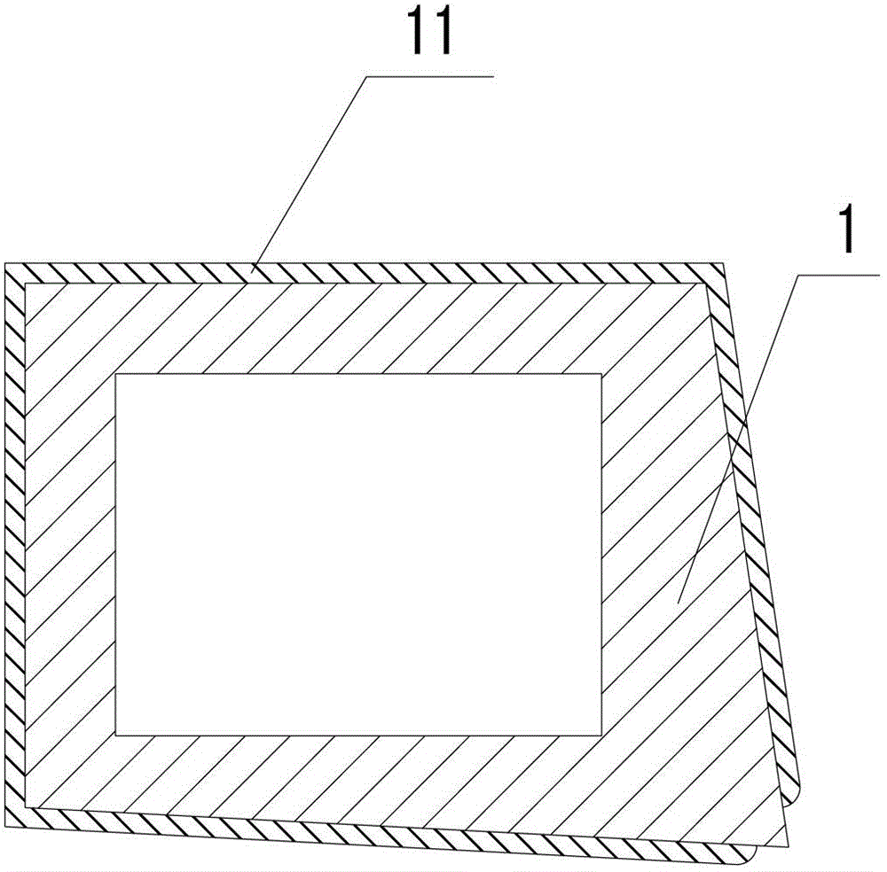
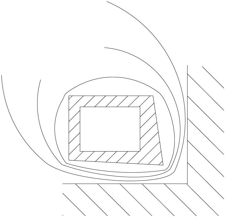
[0044] The first group of preferred embodiments: as Figure 1 to Figure 4 As shown, the quenching inductor 1 for shaft parts is an annular body, the annular inner surface 3 of the quenching inductor 1 is a tapered surface corresponding to the cylindrical surface 101 of the shaft parts to be quenched, and the annular inner surface of the quenching inductor 1 The angle between 3 and the cylindrical surface 101 of the shaft part to be quenched is α; the bottom surface 4 of the quenching inductor 1 is an inclined plane corresponding to the lower end surface 102 of the shaft part to be quenched, and the bottom surface 4 of the quenching inductor 1 and the shaft to be quenched The included angle between the lower end surfaces 102 of the parts is β.

[0045]A journal (not shown in the figure) is formed at...


PUM


Abstract

The invention discloses a quenching inductor for shaft parts and a quenching method, which are designed for solving the problem of poor quenching effect of shaft necks of existing shaft parts. The quenching inductor for the shaft parts is a ring-shaped body, wherein the inner surface of the quenching inductor is a conical surface, and the bottom surface of the quenching inductor is an inclined surface. A self-cooling water channel and a quenching liquid channel of the inductor are formed in a cavity. Magnet conduction layers are formed on the outer surface, the inner surface, the top surface and the bottom surface of the quenching inductor. A quenching system for the shaft parts comprises the shaft parts and the quenching inductor for the shaft parts. According to the quenching method, an included angle is formed between the inner surface and the cylindrical surface of the inductor, and an included angle is formed between the bottom surface and the lower end face of the inductor. The quenching inductor and system for the shaft parts are reasonable in structure, convenient to use and low in manufacture cost, and are suitable for the shaft parts including hollow shaft parts and thin-walled tubes. The quenching method is simple in procedure and has low requirements on hardware such as a device.

Description

technical field [0001] The invention relates to a quenching inductor and a quenching method, in particular to a quenching inductor and a quenching method for shaft parts. Background technique [0002] It is a very important process to quench the shaft neck (the junction of the cylindrical surface and the lower end surface) of shaft parts (including hollow shaft parts and thin-walled tubes). Among them, the long / short hollow shaft rotary structure is the key part of the modern photoelectric turntable. In order to not only ensure the high precision of the photoelectric system in the long-term working state, but also enhance the ability of the vehicle to resist strong impact and vibration, it is required that the shaft parts be near The right-angle guide rail is partially quenched and strengthened, and at the same time, the rest of the shaft parts cannot be deformed by heat. [0003] Among the existing quenching methods, the laser quenching method easily leads to unstable qual...

Claims


Application Information

Patent Timeline
Patent Type & Authority Patents(China)
IPC IPC(8): C21D1/42C21D1/667C21D9/00C21D1/18
CPCY02P10/25
Inventor 施建华赵钰辉王以琦刘滨李勇怀郑练彭光宇马丹王克伟苏震马丽林李超申江勇郭俊亮韩方丁顾非
Owner CHINA NORTH IND NEW TECH PROMOTION INST
Why Eureka
Try Eureka