Filter device with heating device used for heating medium

A technology of filtering device and heating device, which can be used in filtering separation, muffler device, exhaust device, etc., can solve problems such as troublesome and achieve the effect of reducing injection molding cost, less material consumption, and light price

Active Publication Date: 2013-06-26
ROBERT BOSCH GMBH
View PDF7 Cites 4 Cited by
  • Summary
  • Abstract
  • Description
  • Claims
  • Application Information

AI Technical Summary

Problems solved by technology

However, both solutions are relatively labor-intensive and require additional adaptation of components

Method used


Image

  • Filter device with heating device used for heating medium
  • Filter device with heating device used for heating medium

Examples


Embodiment Construction

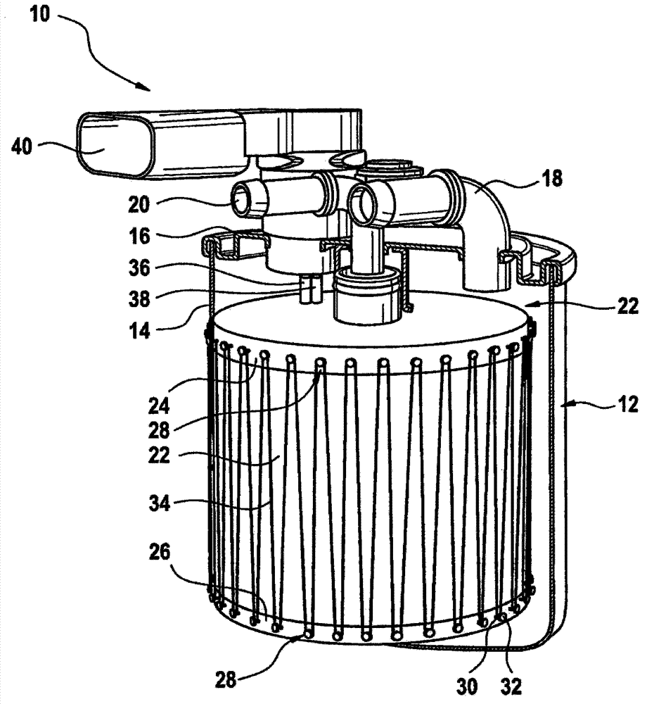
[0018] figure 1 Shown is a filter device 10 which is designed as a fuel filter for a motor vehicle. The filter device 10 is formed with a filter housing 12 formed from a cylindrical housing cup 14 and a circular housing cover 16 closing the housing cup 14 .

[0019] On the housing cover 16 there is a curved, tubular inlet 18 and an identically shaped outlet 20 , which both lead through the housing cover 16 into the interior of the housing cup 14 . In the housing cup 14 there is a hollow-cylindrical filter element 22 which separates the inlet side from the outlet side. The medium, in particular fuel, which flows into the housing cup 14 via the inlet 18 flows through the filter element 22 and removes impurities and water there. The medium then leaves the filter device 10 in purified form through the outlet 20 .

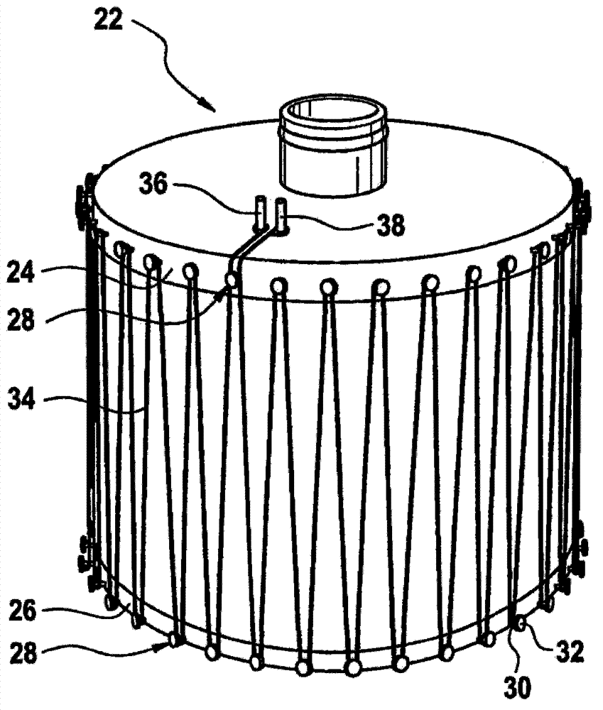
[0020] figure 2 The filter element 22 is shown in detail in . On its upper end-side edge region 24 and on its lower end-side edge region 26 , it each has a row of...


PUM


Abstract

In a filter device (10) with a filter element (22) arranged in a filter casing (12) and with a heating device used for heating the medium flowing through the filter casing (12), the heating device is provided with a heating wire (34) tensioned between at least two supports (28).

Description

technical field [0001] The invention relates to a filter device, in particular a liquid filter, such as a urea filter or a fuel filter, with a filter element arranged in a filter housing and with a heating device for heating a medium flowing through the filter housing. Furthermore, the invention relates to the use of such a filter device as a fuel filter in a motor vehicle. Background technique [0002] Filter devices at low operating temperatures often require a heating device for heating the fluid flowing through, since the viscosity of the medium to be filtered therein increases at low temperatures and thereafter it becomes difficult to pass the medium through the corresponding filter element. difficulty. In diesel filters, for example, problems can arise if the outside temperature falls below the so-called fuel CFPP (cold filter point) during a cold engine start. In the case of urea filters, a heating unit may be necessary. [0003] The heating device used here is des...

Claims


Application Information

Patent Timeline
Patent Type & Authority Applications(China)
IPC IPC(8): F01N3/10B01D53/94
CPCB01D35/18B01D27/08F02M37/30
Inventor C·波塞尔马格努恩V·戈梅斯伽玛
Owner ROBERT BOSCH GMBH
Why Eureka
Try Eureka