Fuel cell energy recovery system and control method

An energy recovery and fuel cell technology, used in fuel cells, fuel cell additives, fuel cell heat exchange, etc. Pressure and other problems, to achieve the effect of high energy utilization efficiency, enhanced work ability, and fine utilization

Pending Publication Date: 2022-03-18
蜂巢蔚领动力科技(江苏)有限公司
View PDF12 Cites 1 Cited by
  • Summary
  • Abstract
  • Description
  • Claims
  • Application Information

AI Technical Summary

Problems solved by technology

[0003] The air compressor is the core component of the gas supply system of the fuel cell system. At present, the air compressor for the fuel cell is mainly a single-stage supercharger or a two-stage supercharger system, but both of these technical solutions bring great pressure to the fuel cell system. Due to the huge parasitic power consumption, the system cannot effectively use the fuel cell stack reaction products, heat, pressure and other energy, which restricts the efficiency improvement of the fuel cell system and even the entire vehicle. Now some systems with expansion ends have been developed to deal with The exhaust energy of the stack is recovered, but it is rarely commercialized

Method used


Image

  • Fuel cell energy recovery system and control method
  • Fuel cell energy recovery system and control method
  • Fuel cell energy recovery system and control method

Examples


Embodiment 1

[0038] refer to Figure 1-5 and Figure 9 , is the first embodiment of the present invention, which provides a fuel cell energy recovery system, the fuel cell energy recovery system includes a recovery unit 100, and the recovery unit 100 includes a primary recovery module 101 and a secondary recovery module 102.

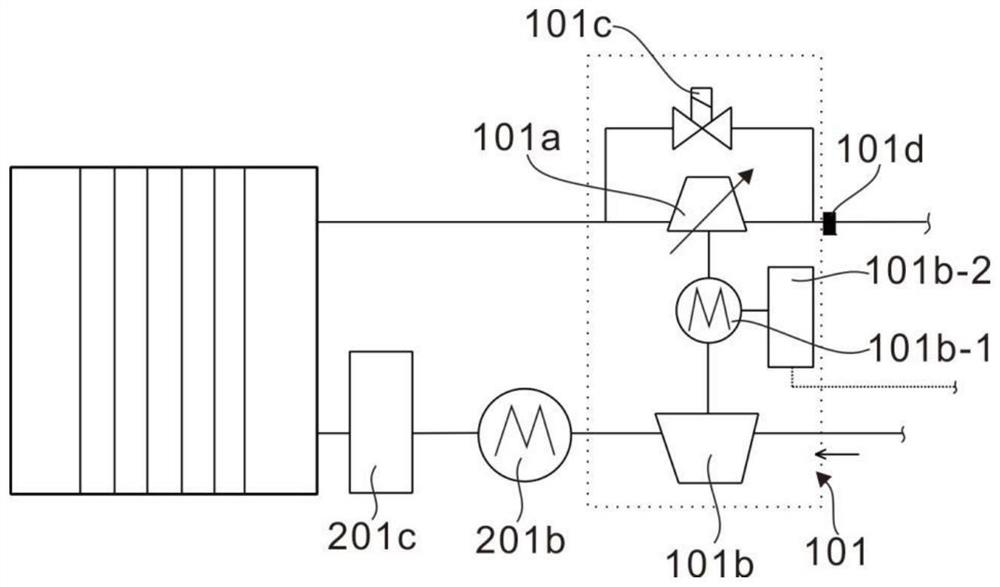
[0039] Specifically, the primary recovery module 101 includes a primary expansion end 101a, an air compressor 101b, and a first bypass valve 101c, the primary expansion end 101a is coaxially connected to the air compressor 101b, and the first bypass valve 101c is connected to a The two ends of the expansion end 101a of the first stage, the air compressor 101b is used for forced air intake to supply air for the fuel cell, and the high-temperature steam passes through the expansion end 101a of the first stage of the coaxial connection of the air compressor 101, using temperature, pressure and speed energy Blow the turbine in the first-stage expansion end 101a to do wo...

Embodiment 2

[0045] refer to image 3 and Figure 6~7 , is the second embodiment of the present invention, which is based on the previous embodiment.

[0046] Specifically, the air compressor 101b includes a motor 101b-1 and a motor controller 101b-2, the motor 101b-1 is connected to the air compressor 101b and the primary expansion end 101a, and the motor controller 101b-2 is connected to the motor 101b-1 Connected, the motor 101b-1 is used to control the start of the air compressor 101b.

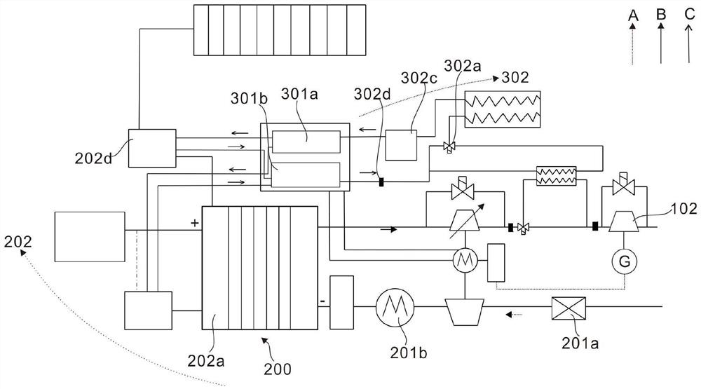
[0047] Further, it also includes a fuel reaction unit 200, the fuel reaction unit 200 includes an air supply module 201, the air supply module 201 includes an air filter 201a, an intercooler 201b and a humidifier 201c, and the air filter 201a is connected to the air compressor 101b , the intercooler 201b is connected to the air compressor 101b, the humidifier 201c is connected to the intercooler 201b, the air filter 201a is used to filter the inhaled air, and the intercooler 201b is used to reduce th...

Embodiment 3

[0052] refer to image 3 and Figure 7-9 , is the third embodiment of the present invention, which is based on the first two embodiments.

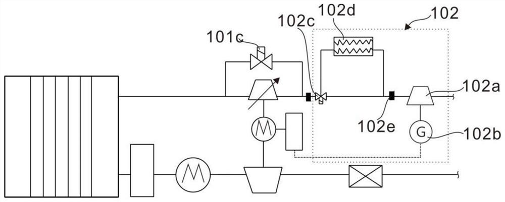
[0053] Specifically, the secondary recovery module 102 also includes a first three-way valve 102c, a heat exchanger 102d and a first sensor 102e, the first three-way valve 102c is connected to the primary expansion end 101a; one end of the heat exchanger 102d is connected to the first A three-way valve 102c is connected, and the other end is connected with the secondary expansion end 102a; the first sensor 102e is arranged upstream of the secondary expansion end 102a, and the first three-way valve 102c is used to control the exhaust gas to pass through the first recovery module 101 After energy recovery, whether to exchange heat with the heat-absorbing coolant through the heat exchanger 102d? If the first three-way valve 102c is connected to the heat exchanger 102d, the exhaust gas will enter the heat exchanger 102d to exchange heat with ...


PUM


Abstract

The invention discloses a fuel cell energy recovery system and a control method.The fuel cell energy recovery system comprises a recovery unit, a fuel reaction unit and a cooling unit, the recovery unit comprises a primary recovery module and a secondary recovery module, and the primary recovery module comprises a primary expansion end, an air compressor and a second sensor; the primary expansion end is an electric adjustable expansion end, so that the system can effectively recover energy in tail gas of the fuel cell at low-speed, medium-speed and high-speed stages, the secondary recovery module comprises a secondary expansion end, a generator and a first sensor, and the cooling unit comprises a third sensor. The invention also discloses a control method of the fuel cell energy recovery system. The fine management of the energy of the whole system can be realized through a sensor in the system and a special structural design.

Description

technical field [0001] The invention relates to the technical field of fuel cell energy recovery, in particular to a fuel cell energy recovery system and a control method. Background technique [0002] As energy shortages and environmental problems become prominent, and emission regulations are tightened, fuel cell technology is gradually receiving more and more attention. Hydrogen fuel cell is a chemical device that directly converts chemical energy into electrical energy, also known as chemical generation. Its working principle is a device that converts the chemical energy of hydrogen and oxygen reaction into electrical energy. Hydrogen fuel cell technology is considered to be an important link in the transformation of transportation energy and power, and has attracted much attention. Proton exchange membrane fuel cell is the current fuel cell family The most mature representative, it uses hydrogen and air (oxygen in the air) as fuel to undergo an electrochemical reaction,...

Claims


Application Information

Patent Timeline
Patent Type & Authority Applications(China)
IPC IPC(8): F01D15/08F01D17/10F01D13/02F01D15/10F01K7/22F04B35/02F04B35/04F04B41/06H01M8/04007H01M8/04111
CPCF01D15/08F01D17/105F01D13/02F01D15/10F01K7/22F04B35/00F04B35/04F04B41/06H01M8/04111H01M8/04007Y02E60/50
Inventor 牛鹏飞张泽裕崔玺魏明波康明龙崔钊辉连永鹏
Owner 蜂巢蔚领动力科技(江苏)有限公司
Why Eureka
Try Eureka