Flanging finite element modeling method

A modeling method and finite element technology, applied in special data processing applications, instruments, electrical digital data processing, etc., can solve the problem of inability to simulate the connection of hem glue, rough modeling requirements, and no way to simulate hem Glue connection and other issues

Inactive Publication Date: 2013-06-26
SAIC MOTOR
View PDF2 Cites 7 Cited by
  • Summary
  • Abstract
  • Description
  • Claims
  • Application Information

AI Technical Summary

Problems solved by technology

[0005] The modeling method of the above-mentioned first type of flanging simulation technology is simple, and there is no special requirement for mesh division, but it cannot accurately simulate the function of the flanging bend, and there is no way to simulate the bending between the inner and outer plate flanging. The connection effect of the edge glue, so the simulated effect is rough
[0006] Compared with the modeling method o

Method used


Image

  • Flanging finite element modeling method
  • Flanging finite element modeling method
  • Flanging finite element modeling method

Examples


Embodiment Construction

[0021] The embodiment of the present invention will be described in detail below with reference to the description of the flanging of the engine cover with reference to FIG. 3 . It should be noted that the features specifically described in the embodiments should not be understood as necessary or unique features for realizing the present invention, and those skilled in the art can understand that these features may be illustrative rather than limiting.

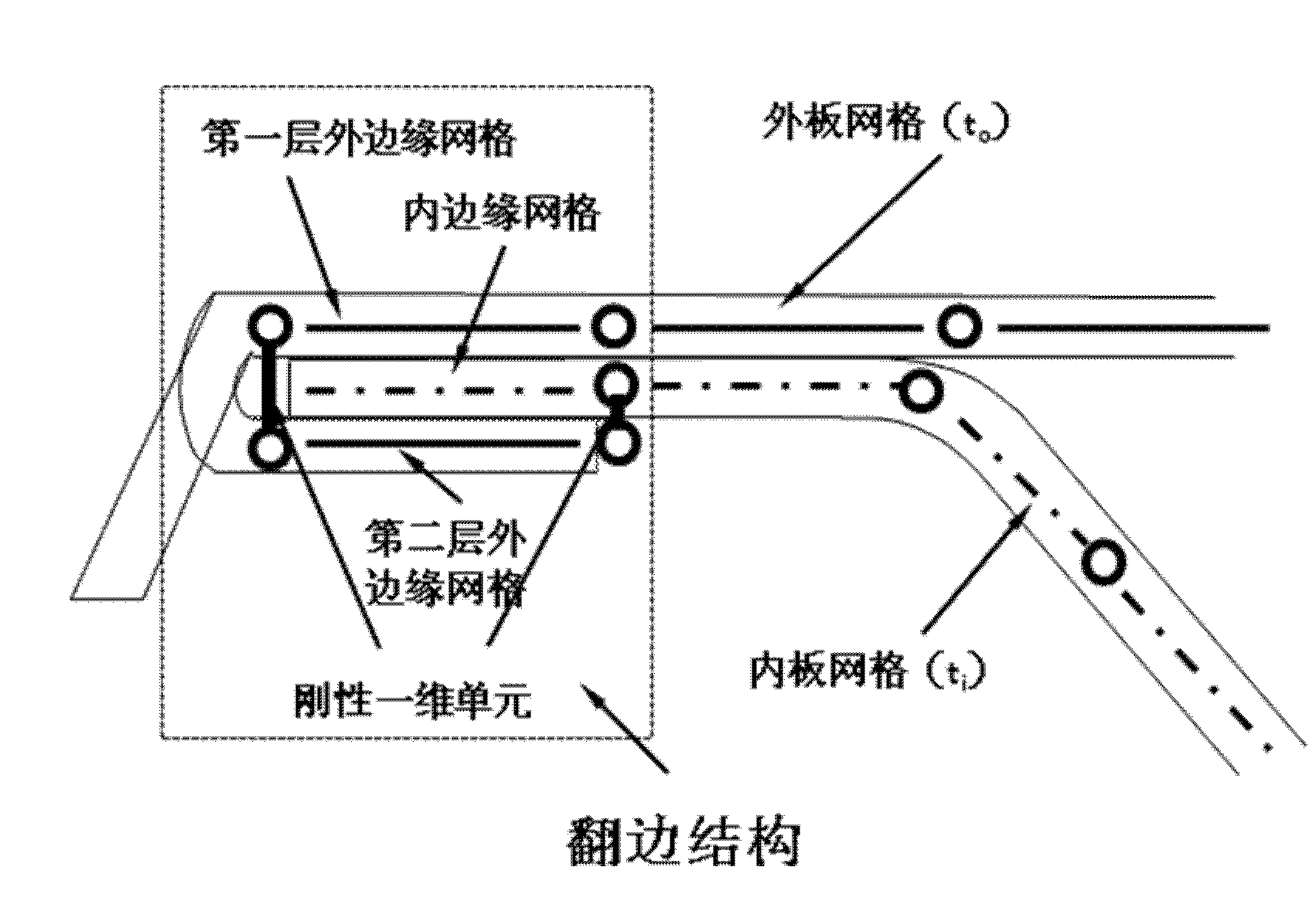
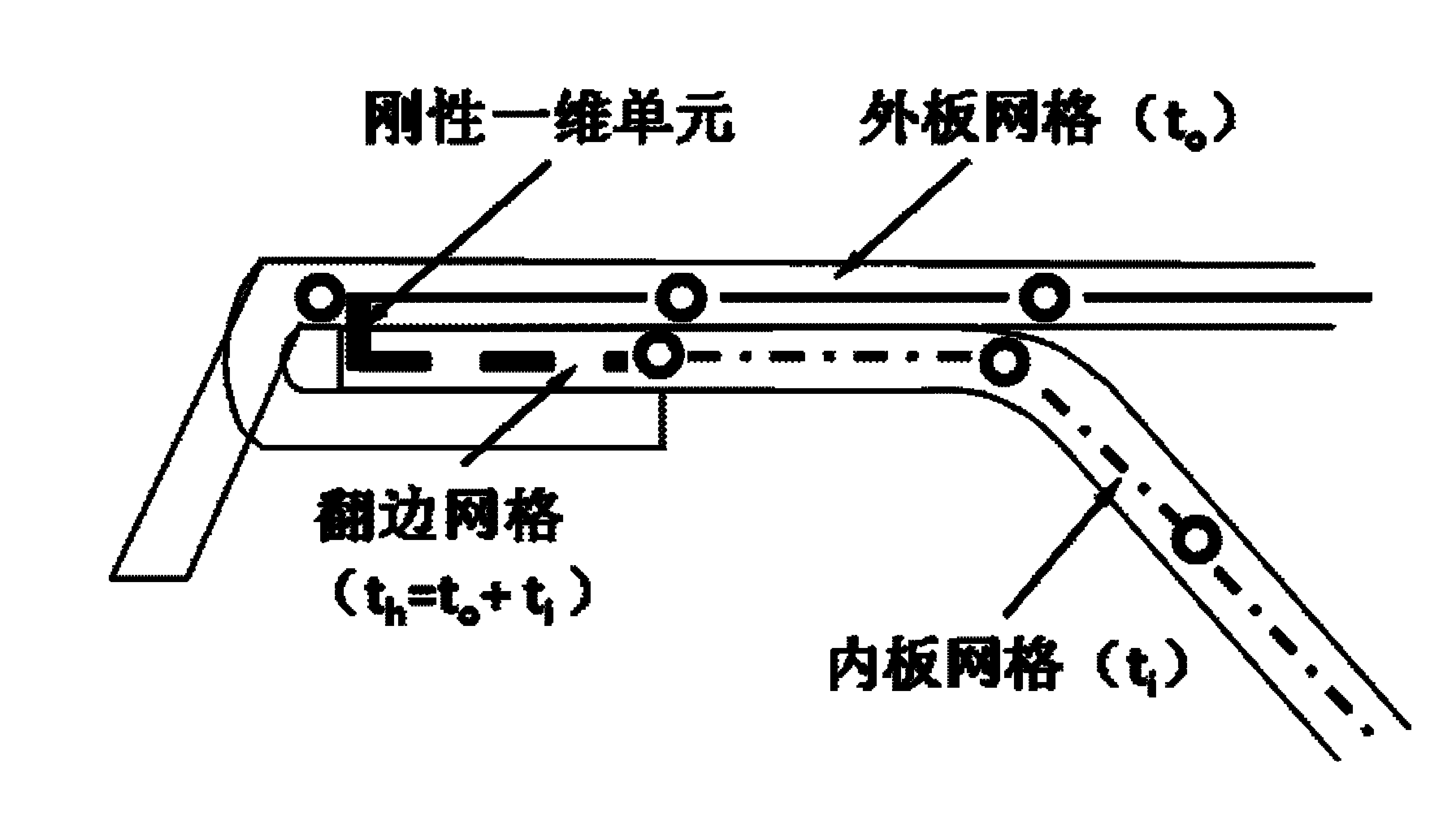
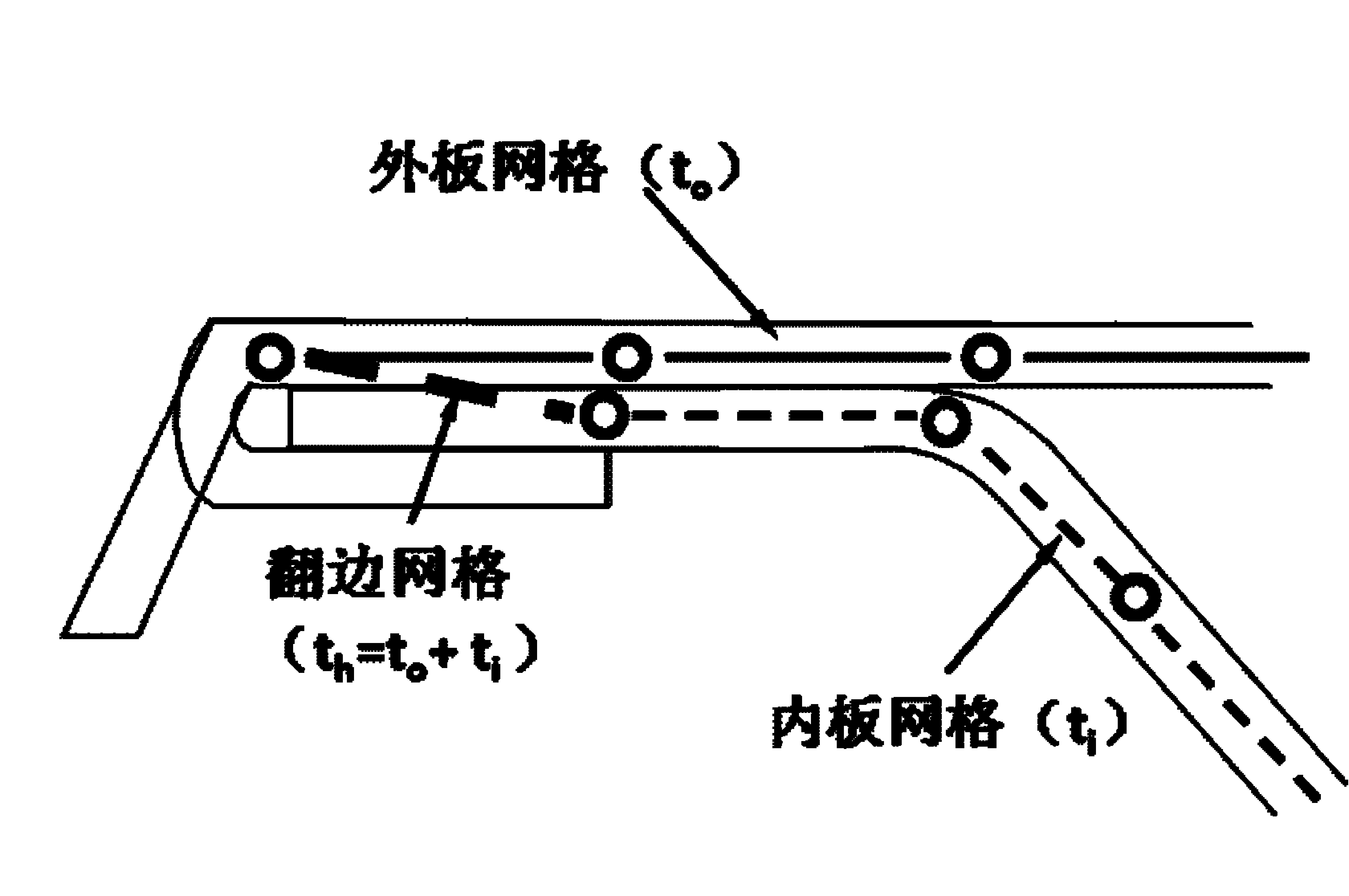
[0022] The whole flange structure according to the present invention can be simulated by four components, namely, the first layer outer edge, the second layer outer edge, the inner edge and the one-dimensional rigid unit. Set the thickness of the inner plate to 0.7mm, and the thickness of the outer plate to 0.8mm. details as follows:

[0023] Step 1: Modeling of the inner edge of the bonnet (i.e. the engine cover), which may include:

[0024] a. Extraction of the geometric middle surface of the inner panel flanging: accordin...


PUM


Abstract

The invention discloses a flanging finite element modeling method. The flanging finite element modeling method comprises the steps of conducting finite element modeling to the inner edge of a flanging to obtain inner edge grids; conducting finite element modeling to the outer edge of the flange to obtain a first layer of outer edge grids and a second layer of outer edge grids; and conducting finite element modeling to the outer edge bending portion of the flanging to obtain a bending unit, and conducting finite element modeling to folding glue between the inner edge and the outer edge to obtain a folding glue unit. According to the flanging finite element modeling method, the real structure of the flanging can be accurately reflected, and reliable support is supplied to optimization and improvement of the flanging.

Description

technical field [0001] The invention relates to the field of computer-aided engineering, in particular to a finite element modeling method for a cover flange based on the durability analysis of an automobile structure. Background technique [0002] After nearly a hundred years of development, flanging technology has been widely used in automobile panels. The term flanging here refers to the folding of the outer panel at the edge of the cover over the inner panel and bonding it to the inner panel with hemming glue. Some high-end cars even arrange welding spots locally to strengthen the connection. The use of this technology not only makes the edges of the cover more beautiful, but also improves the customer's perception of the quality of the product, so this technology is currently applied to almost all models. [0003] With the rapid development of computer software and hardware technology, computer-aided engineering (CAE) technology is getting more and more attention from...

Claims


Application Information

Patent Timeline
IPC IPC(8): G06F17/50
Inventor 王国明黄涛夏晨翔姜辉王光耀孙成智戴轶
Owner SAIC MOTOR
Why Eureka
Try Eureka