Keyboard device with light emitting key

A keyboard device and button technology, which is applied in the direction of emergency protection devices, legends, electrical components, etc., can solve the problems of whether the key 21 is not easy to emit light, assembly error, poor operating feel, etc., and achieve good operating feel and small size.

Inactive Publication Date: 2013-06-26
PRIMAX ELECTRONICS LTD
View PDF5 Cites 5 Cited by
  • Summary
  • Abstract
  • Description
  • Claims
  • Application Information

AI Technical Summary

Problems solved by technology

[0008] In the light-emitting button 21, the shading cover 213 is attached to the plastic film 25 in an adhesive manner, and such a combination method is likely to cause many problems: first, in the process of adhering the shading cover 213 on the plastic film 25, the shading cover 213 is attached to the plastic film 25. 213 is prone to positional displacement and cannot align the opening 2131 of the light shield 213 with the light-emitting element 23, so that only part of the light beam generated by the light-emitting element 23 can pass through the opening 2131, while the other part of the light beam is blocked. Cover 213 blocks, so it will cause the luminous effect of the luminous button 21 is not obvious and it is not easy to distinguish whether the luminous button 21 is luminous
Second, an assembly error is likely to occur between the light shield 213 and the plastic film 25, so that the light shield 213 of the keyboard 2 after manufacture is easy to fall off, and when the light shield 213 falls off, the light beam produced by the light emitting element 23 cannot Concentrated by the hood 213 and diverged to all directions, it also causes the problem that the luminous effect of the luminous button 21 is not obvious
That is to say, when the user touches the key cap 211, the user will have a bad operating feeling due to the interference of the light shield 213 on the key cap 211.

Method used


Image

  • Keyboard device with light emitting key
  • Keyboard device with light emitting key
  • Keyboard device with light emitting key

Examples


Embodiment Construction

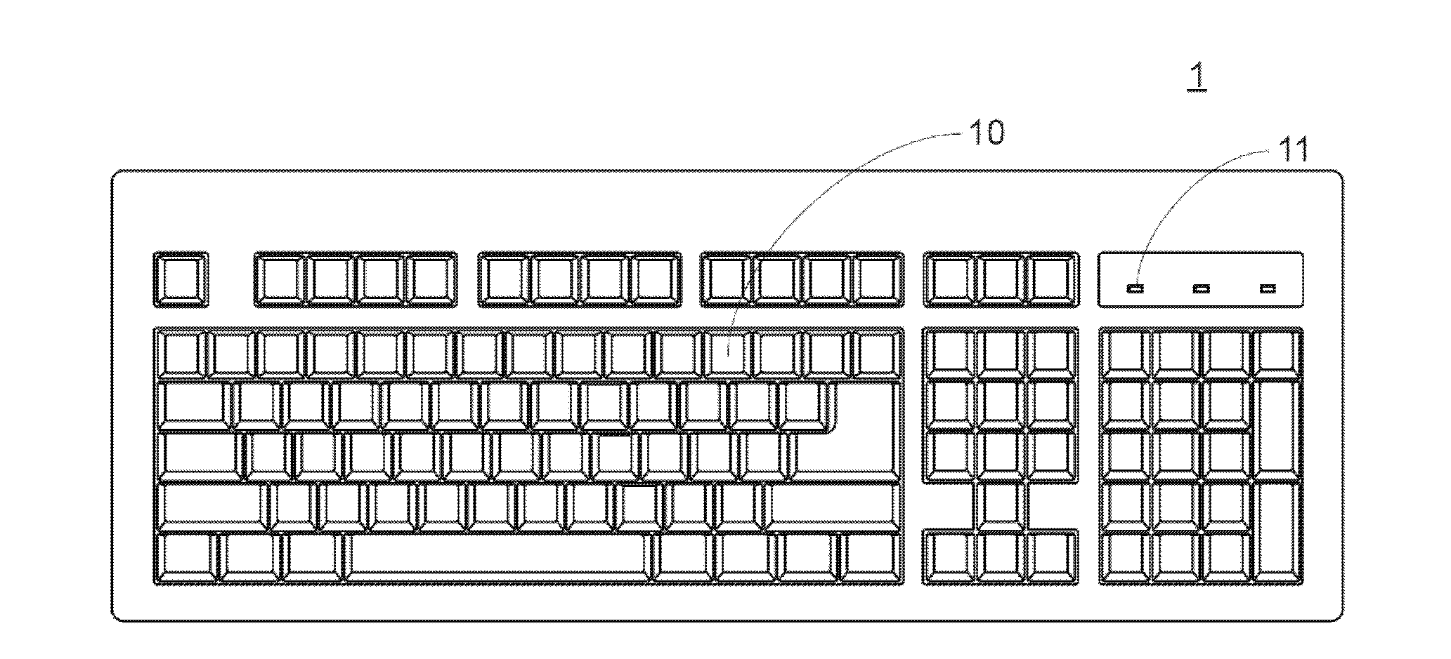
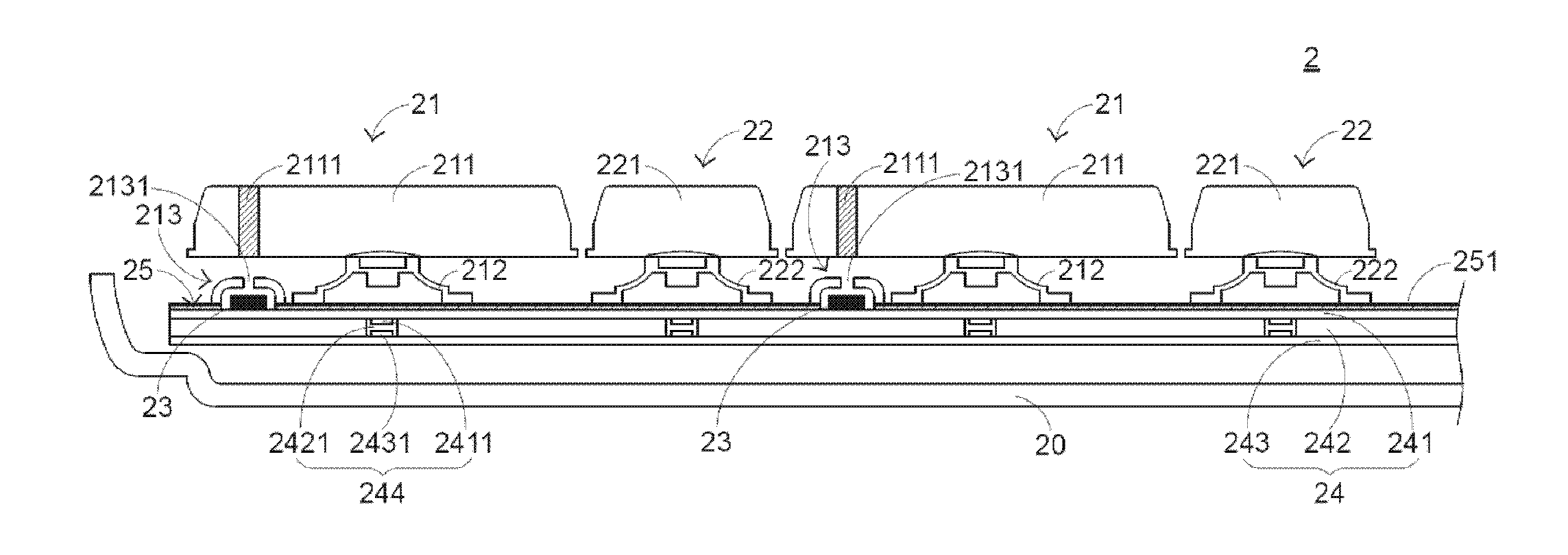
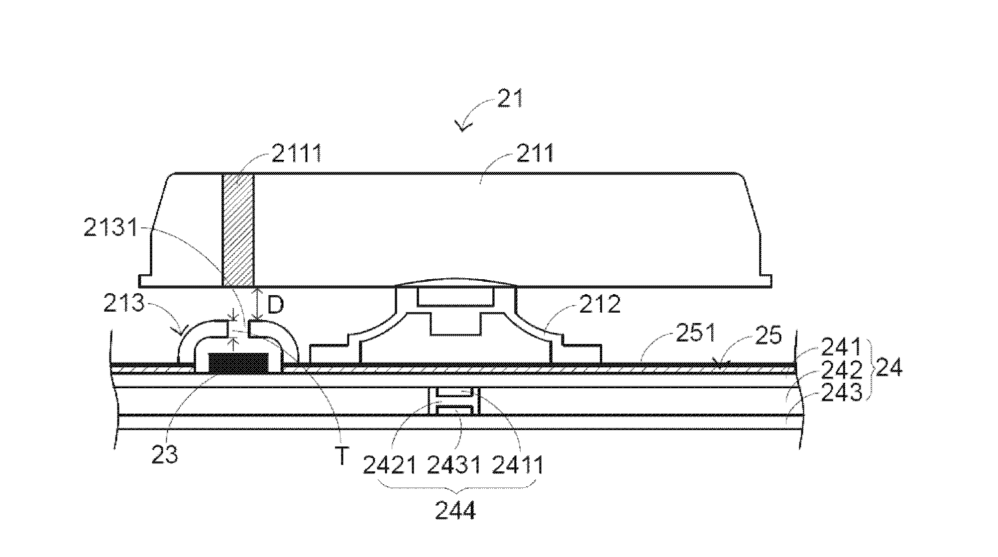
[0029] In view of the defects in the prior art, the present invention provides a keyboard device with luminous keys and good operating feel. Please also see Figure 4 as well as Figure 5 , Figure 4 It is a schematic structural diagram of a keyboard device with light-emitting keys in a preferred embodiment of the present invention, and Figure 5 It is a schematic cross-sectional view of a partial structure of a keyboard device with light-emitting keys in a preferred embodiment of the present invention. The keyboard device 3 with luminous keys includes a bottom plate 30 , at least one luminous key 31 , a plurality of keys 32 , a plurality of luminous elements 33 , a membrane switch circuit 34 , an opaque sealant 35 and a transparent sealant 36 . The bottom plate 30 is disposed under the membrane switch circuit 34 for carrying at least one light-emitting button 31 , a plurality of buttons 32 , a plurality of light-emitting elements 33 and the membrane switch circuit 34 .

...


PUM


Abstract

The invention relates to a keyboard device with a light emitting key. The keyboard device comprises at least one light emitting key, at least one light emitting component, a thin film switching circuit, light-proof sealing compound and light-transmitting sealing compound. The light emitting key is provided with a light-transmitting area, and the light emitting component is electrically connected with the thin film switching circuit and arranged below the light-transmitting area. The light-transmitting sealing compound is used for wrapping the upper surface of the light emitting component, the light-proof sealing compound partially wraps the light-transmitting sealing compound, and light beams generated by the light emitting component can penetrate through the light-transmitting sealing compound to be projected to the light-transmitting area. The keyboard device solves the problem in the existing keyboard device with the light emitting key that a light shading cover falls off and guarantees good operation touch.

Description

technical field [0001] The present invention relates to a keyboard device, in particular to a keyboard device with luminous keys. Background technique [0002] Common computer peripheral input devices include mouse devices, keyboard devices, and trackball devices. Among them, the keyboard device can directly input text and symbols to the computer, so it is quite valued by users and input device manufacturers. [0003] Firstly, the structure and function of the existing keyboard device are described, please refer to figure 1 , which is a schematic diagram of the appearance structure of the existing keyboard device. The surface of the existing keyboard device 1 has a plurality of keys 10 and a plurality of indicator lights 11. These keys 10 are classified into general keys, number keys, and function keys. Corresponding signals are given to the computer to make the computer perform the functions of the pressed keys, such as general keys for inputting symbols such as English l...

Claims


Application Information

Patent Timeline
Patent Type & Authority Applications(China)
IPC IPC(8): H01H13/83
CPCH01H13/83H01H3/125H01H13/702H01H2219/039H01H2221/07
Inventor 范树建郑祥文
Owner PRIMAX ELECTRONICS LTD
Why Eureka
Try Eureka