
Balanced micro-strip line feeding printed V-shaped antenna with loading metal disc

A technology for balancing microstrip lines and metal discs, applied to antennas, resonant antennas, electrical components, etc., can solve the problems of complex feeding structure and loss, and achieve the effect of improving gain characteristics, small size, and wide application range

Inactive Publication Date: 2013-06-26
HARBIN INST OF TECH
View PDF2 Cites 5 Cited by
  • Summary
  • Abstract
  • Description
  • Claims
  • Application Information

AI Technical Summary

Problems solved by technology

[0004] In order to solve the problem that the traditional traveling wave antenna needs to introduce a lossy terminal matching load to realize the traveling wave working mode, and the feeding structure is complicated, the invention further proposes a printed V-shaped antenna with balanced microstrip line feeding and loading metal discs

Method used


Image

  • Balanced micro-strip line feeding printed V-shaped antenna with loading metal disc
  • Balanced micro-strip line feeding printed V-shaped antenna with loading metal disc
  • Balanced micro-strip line feeding printed V-shaped antenna with loading metal disc

Examples


specific Embodiment approach 1

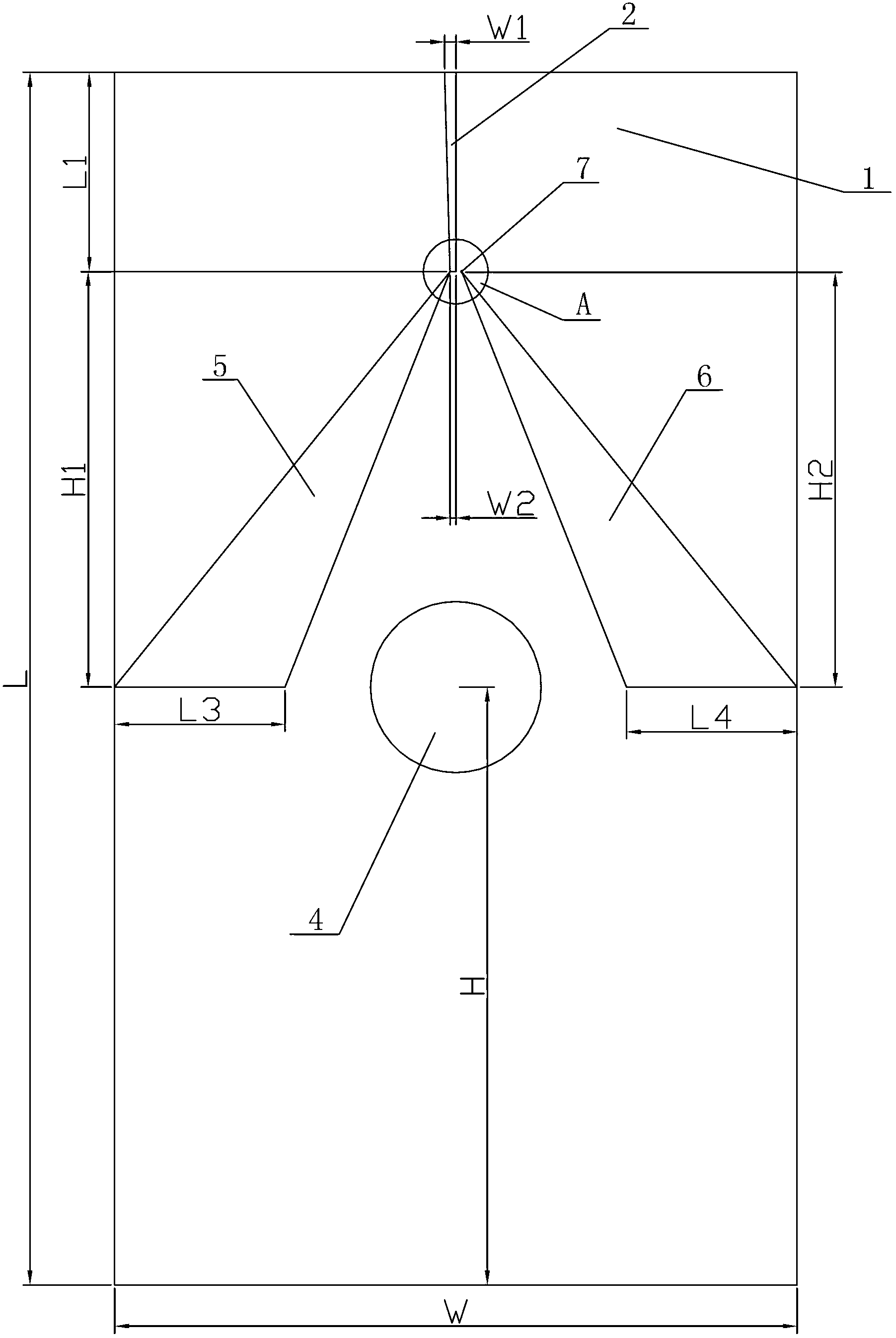
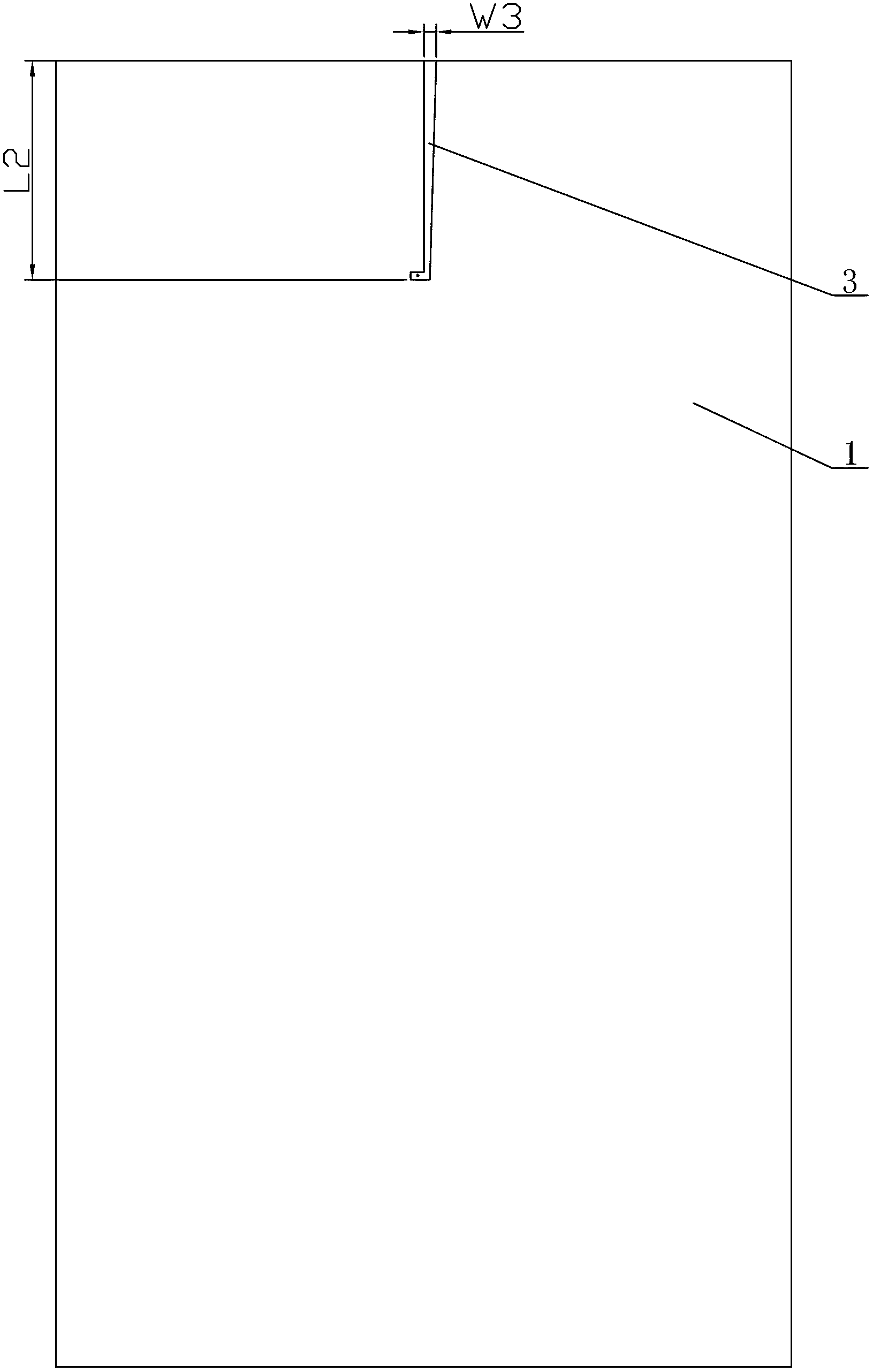
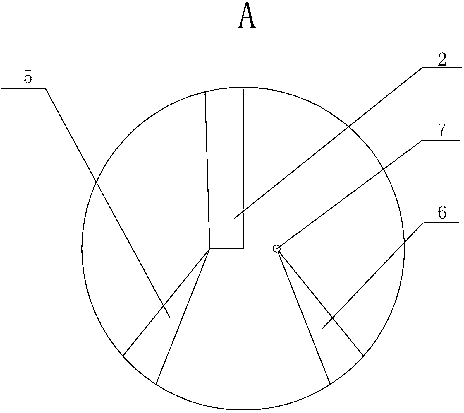
[0008] Specific implementation mode one: combine Figure 1 to Figure 3 Describe this embodiment, the printed V-shaped antenna of the balanced microstrip line feeding loaded metal disc in this embodiment includes a dielectric board 1, a first feeding structure 2, a second feeding structure 3, and a metal disc 4 , the first radiating unit 5 and the second radiating unit 6, the first feeding structure 2 is printed in the middle of the upper end of the front surface of the dielectric board 1 from top to bottom, and the upper end of the first feeding structure 2 is in contact with the dielectric board 1 The upper edge of the second feeding structure 3 is printed in the middle of the upper end of the back of the dielectric board 1 from top to bottom, and the upper end of the second feeding structure 3 is in contact with the upper edge of the dielectric board 1. The first radiation The unit 5 and the second radiating unit 6 are arranged in the middle of the front of the dielectric pl...

specific Embodiment approach 2

[0009] Specific implementation mode two: combination figure 1 Describe this embodiment, the dielectric plate 1 of the printed V-shaped antenna of the balanced microstrip line feeding load metal disc described in this embodiment is a dielectric plate 1 made of epoxy glass cloth laminated board, and the relative dielectric of the dielectric plate 1 The constant is 4.4, the length L of the dielectric board 1 is 210mm-215mm, the width W of the dielectric board 1 is 119mm-121mm, and the thickness of the dielectric board 1 is 1.5mm-2.0mm. Other components and connections are the same as those in the first embodiment.

specific Embodiment approach 3

[0010] Specific implementation mode three: combination figure 1 Describe this embodiment, the length L of the dielectric plate 1 of the printed V-shaped antenna of the balanced microstrip line feeding load metal disc described in this embodiment is 213mm, the width W of the dielectric plate 1 is 120mm, and the thickness of the dielectric plate 1 is 1.5mm.

[0011] The technical effect of this embodiment is that the feeding structure of the antenna is simple, and the medium in the radiation direction of the antenna can effectively increase the gain of the antenna, thereby compensating the loss caused by the dielectric plate.

[0012] Other components and connections are the same as those in the second embodiment.


PUM


Abstract

The invention discloses a balanced micro-strip line feeding printed V-shaped antenna with a loading metal disc, and relates to printed V-shaped antennas. The balanced micro-strip line feeding printed V-shaped antenna aims to solve problems that a traveling-wave working mode only can be implemented when a lossy terminal matched a load is added into the traditional traveling-wave antenna and a feeding structure is complicated. The balanced micro-strip line feeding printed V-shaped antenna is characterized in that a first feeding structure is printed in the middle of the upper end of the front surface of a dielectric slab linearly from top to bottom, a second feeding structure is printed in the middle of the upper end of the back surface of the dielectric slab linearly from top to bottom, a first radiation unit and a second radiation unit are arranged in the middle of the front surface of the dielectric slab and form a herringbone, the upper end of the first radiation unit is connected with the lower end of the first feeding structure, the loading metal disc is arranged between the lower end of the first radiation unit and the lower end of the second radiation unit, and a plated-through via hole is arranged at the upper end of the second radiation unit and sequentially runs through the second radiation unit, the dielectric slab and the second feeding structure. The balanced micro-strip line feeding printed V-shaped antenna is used in the radio field.

Description

technical field [0001] The invention relates to a printed V-shaped antenna, in particular to a printed V-shaped antenna fed by a balanced microstrip line and loaded with a metal disc. Background technique [0002] UWB directional antenna has a wide frequency band and good directivity, and can transmit data at high speed in wireless communication, so it has been widely used. The UWB directional printed antennas currently proposed mainly include log-periodic antennas, Archimedes spiral antennas, equiangular spiral antennas, butterfly antennas, tapered slot antennas, and TEM horn antennas. In order to achieve the directivity of the antenna, the antenna designer generally adopts the following methods: 1. For the omnidirectional antenna, the directional radiation is realized by forming an array or adding a metal reflective surface, typically a butterfly antenna, but this will introduce complex feeding Network; 2. The logarithmic periodic antenna is fed from one end of the short ...

Claims


Application Information

Patent Timeline
Patent Type & Authority Applications(China)
IPC IPC(8): H01Q1/38H01Q9/04H01Q13/08
Inventor 林澍张馨月张兴起王立娜张春雷王力卓
Owner HARBIN INST OF TECH
Learn More