Method and device for controlling video terminal and video terminal
A technology of video terminal and location information, applied in color TV parts, TV system parts, TV and other directions, can solve the problems of single interaction mode, poor versatility, and inflexible operation control.
- Summary
- Abstract
- Description
- Claims
- Application Information
AI Technical Summary
Problems solved by technology
Method used
Image
Examples
Embodiment 1
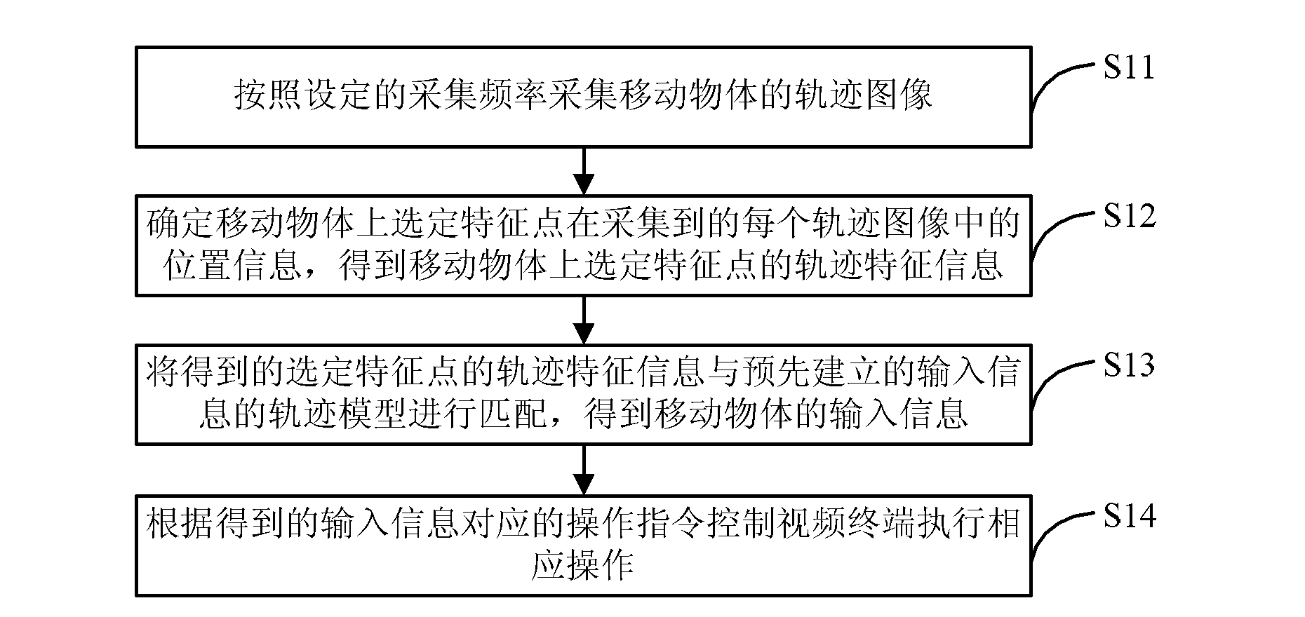
[0081] Embodiment 1 of the present invention provides a video terminal control method. By collecting the trajectory image of the moving object, the trajectory feature information of the selected feature point on the moving object is determined, so as to obtain the corresponding input information, and then obtain the operation instruction corresponding to the input information. , realize the interpretation and recognition of the trajectory of the moving object, determine the various input information, and correspond to the operation instructions, so as to meet the input control of various possible operation instructions. The process is as follows figure 1 shown, including the following steps:
[0082] S11: Acquiring the track image of the moving object according to the set acquisition frequency.
[0083] When the moving object of the input command is captured, the trajectory image of the moving object is collected according to the set collection frequency. For example, when t...
Embodiment 2
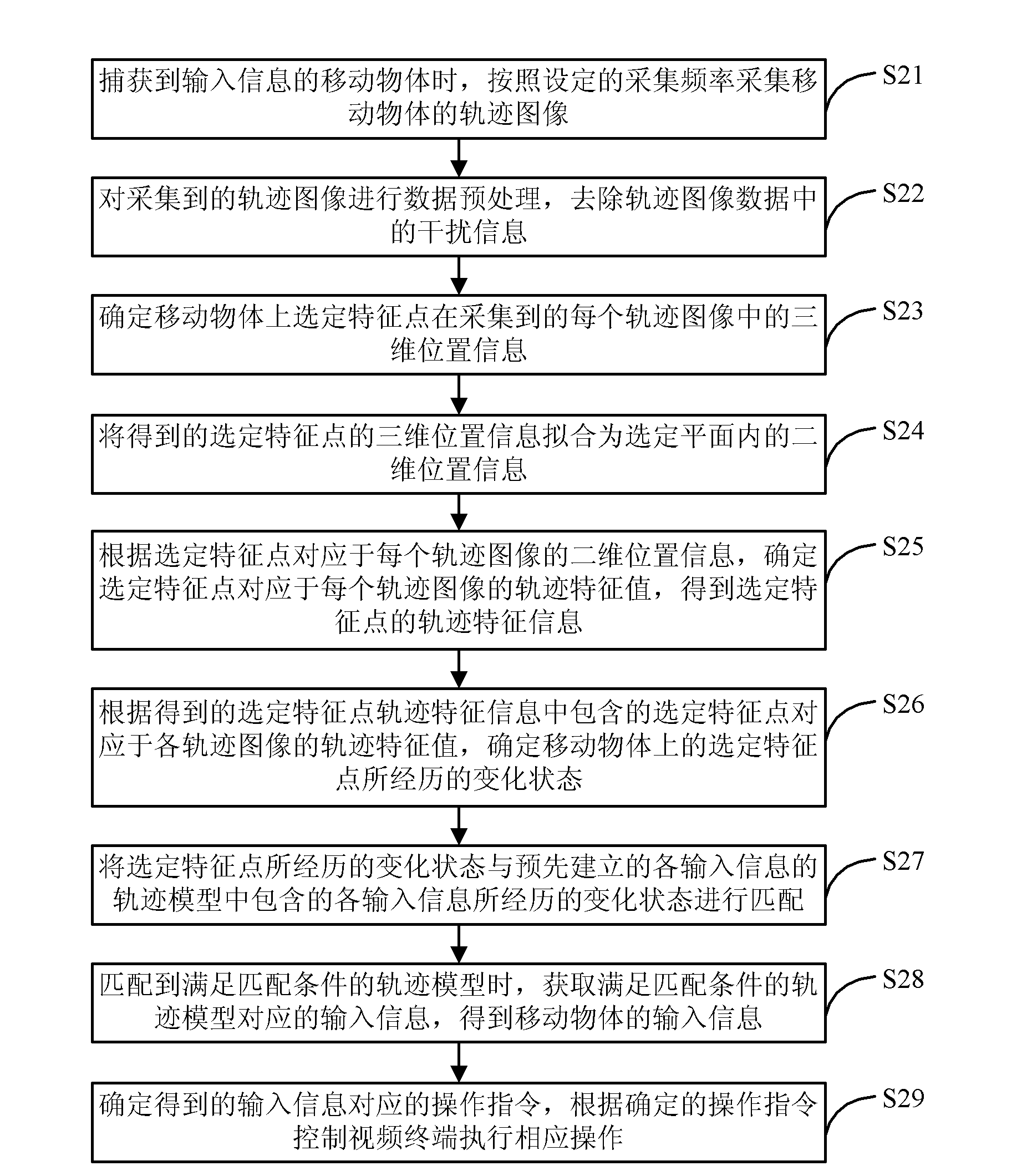
[0097] The video terminal control method provided by Embodiment 2 of the present invention collects three-dimensional position information of selected feature points on a moving object, and then converts it into two-dimensional position information, so as to realize accurate collection of multi-directional input information and make the control of the video terminal more accurate. Flexible and more convenient to operate, the method flow is as follows figure 2 shown, including the following steps:
[0098] S21: When the moving object of the input information is captured, the trajectory image of the moving object is collected according to the set collection frequency.
[0099] See step S11 for details.
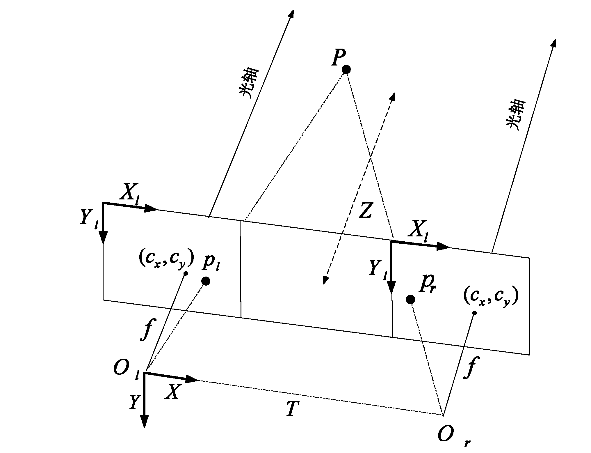
[0100] In this embodiment, the binocular camera is taken as an example. The binocular camera can obtain the depth of field information, so that other interference information can be removed, and the three-dimensional position information such as the three-dimensional space coo...
Embodiment 3
[0172]The video terminal control method provided by Embodiment 3 of the present invention executes different operation processes according to the set current mode, such as terminal control or trajectory model training, and its process is as follows Figure 7 shown, including the following steps:
[0173] S31: When the moving object of the input information is captured, the track image of the moving object is collected according to the set collection frequency.
[0174] Refer to step S11 and step S21, which will not be repeated here.
[0175] S32: Determine the location information of the selected feature points on the moving object in each of the collected trajectory images, and obtain the trajectory feature information of the selected feature points of the moving object according to the determined location information.
[0176] Refer to step S11 and step S23-step S25, which will not be repeated here. It should be noted that, before performing this step, the data preprocessi...
PUM
 Abstract
Description
Claims
Application Information
 - R&D
- Intellectual Property
- Life Sciences
- Materials
- Tech Scout
- Unparalleled Data Quality
- Higher Quality Content
- 60% Fewer Hallucinations
Browse by: Latest US Patents, China's latest patents, Technical Efficacy Thesaurus, Application Domain, Technology Topic, Popular Technical Reports.
© 2025 PatSnap. All rights reserved.Legal|Privacy policy|Modern Slavery Act Transparency Statement|Sitemap|About US| Contact US: help@patsnap.com


