Piston rod for a container

A piston rod and piston technology, applied in the field of piston rods, can solve the problems of large space and asymmetric shape, and achieve the effect of symmetrical shape, easy storage, and easy packaging

Active Publication Date: 2013-06-26
BECTON DICKINSON FRANCE
View PDF4 Cites 3 Cited by
  • Summary
  • Abstract
  • Description
  • Claims
  • Application Information

AI Technical Summary

Problems solved by technology

[0008] However, according to the shape of the piston rod, the injection devices of the prior art also take up a lot of space, at least in width, but also in length, and they are not a suitable solution because their shape is not symmetrical

Method used


Image

  • Piston rod for a container
  • Piston rod for a container
  • Piston rod for a container

Examples


Embodiment Construction

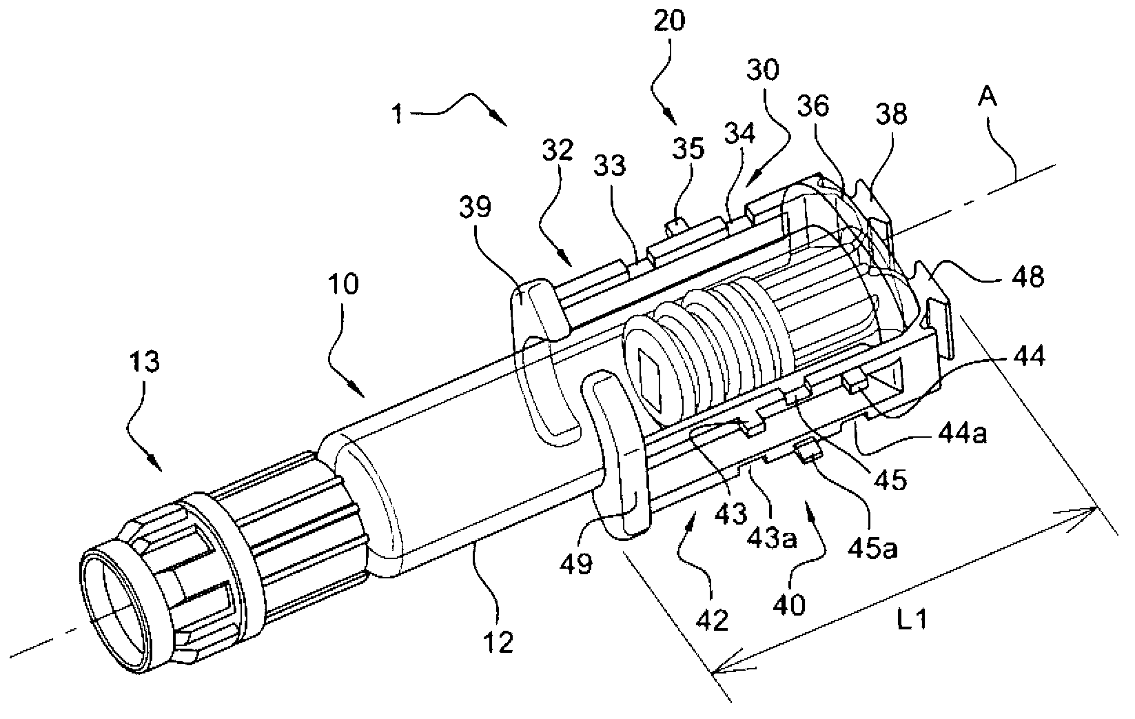
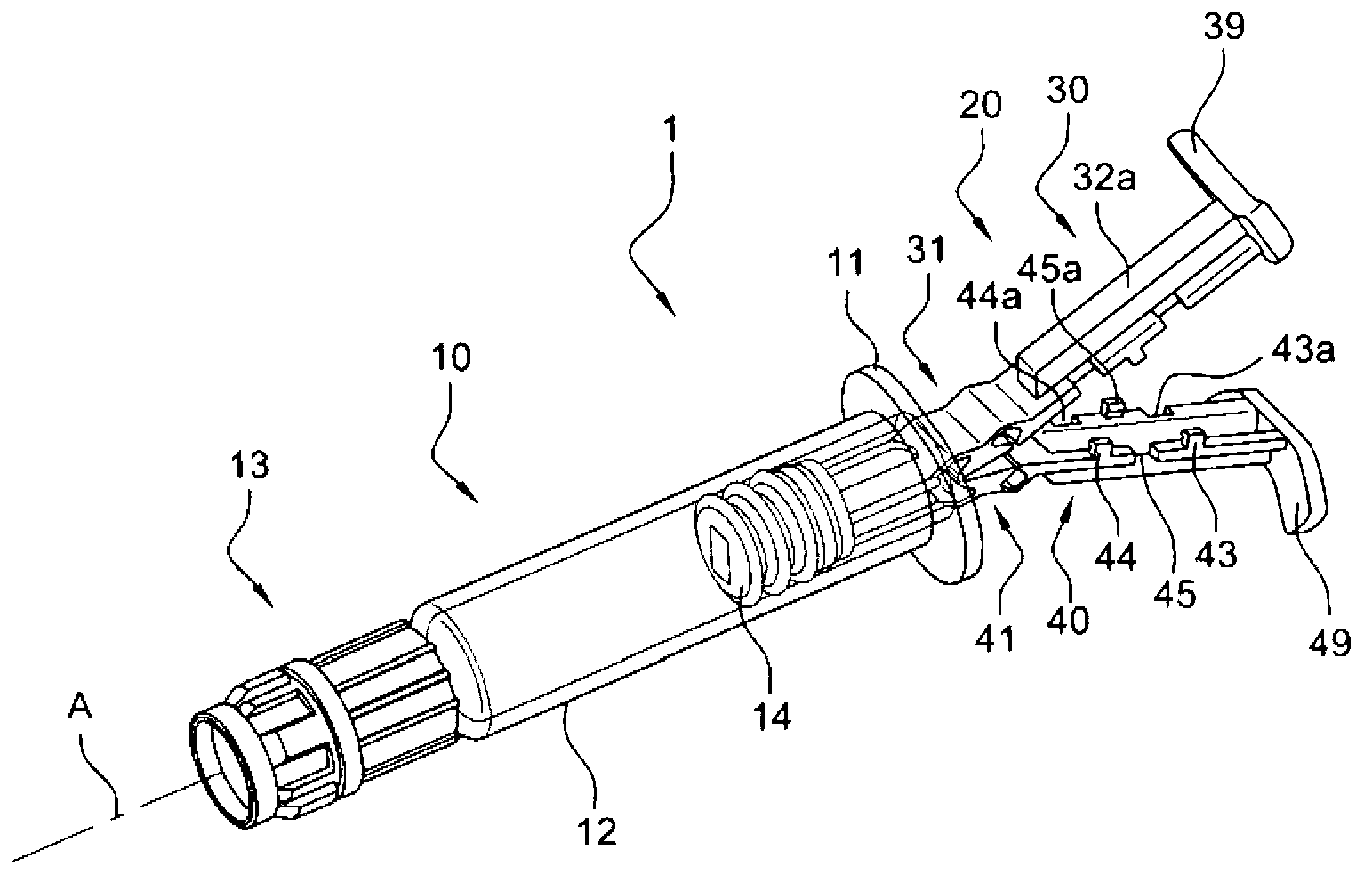
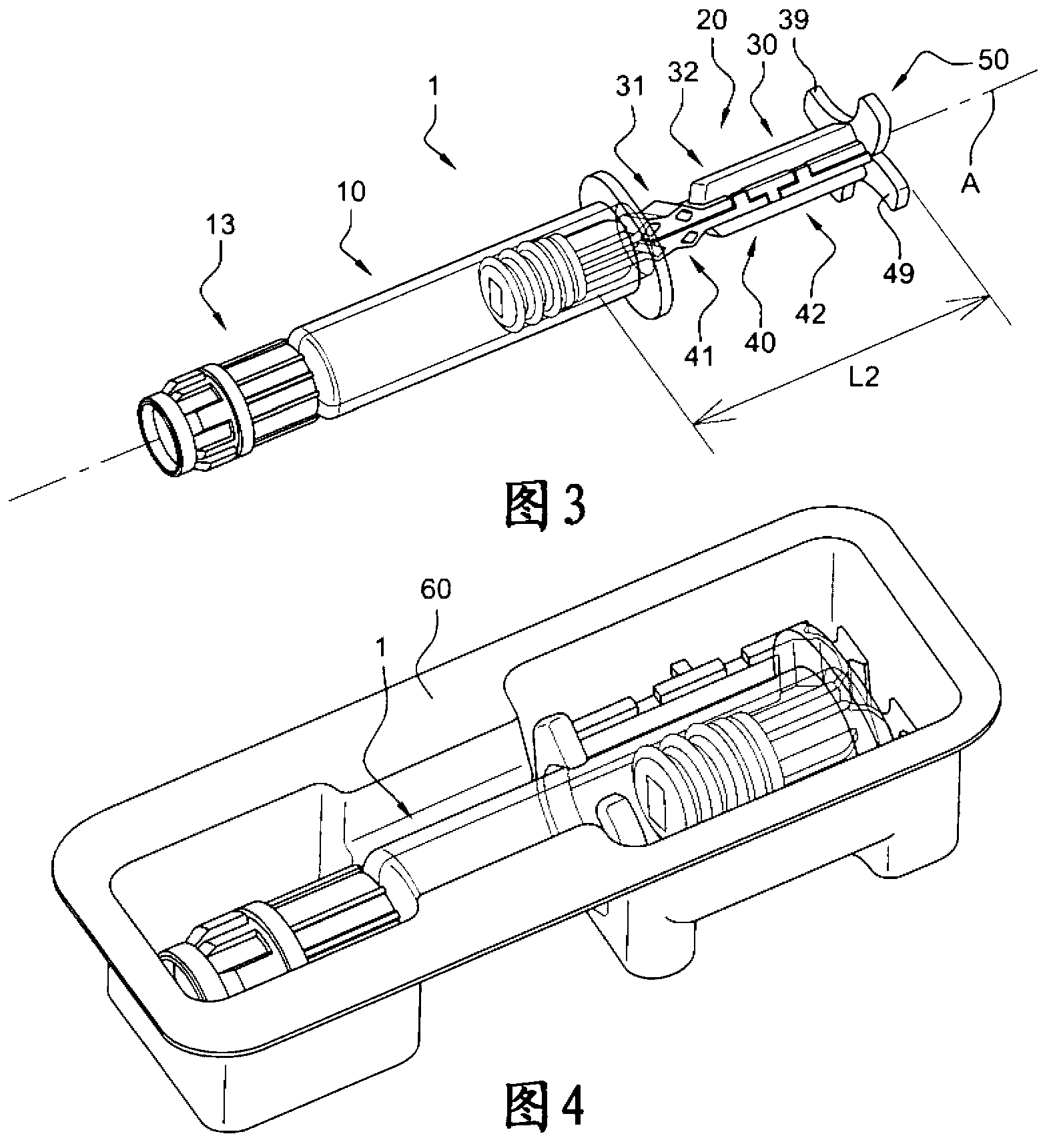
[0060] refer to Figure 1-3 , shows a kit 1 according to the invention comprising a container 10 combined with a piston rod 20 according to the invention. In these figures, the piston rod 20 is mounted on the container 10 so as to form an injection device.

[0061] In the example shown, the container 10 is a syringe body formed by a tubular barrel 12 provided at its proximal end with a flange 11 (see figure 2 ). The flange 11 will constitute a bearing surface for the user's finger when the injection is being made. The distal end of the container 10 is provided with a port for receiving an injection needle: in the embodiment shown in the figures, this port and this needle are not visible because the distal end of the container 10 is closed by a cap 13 . Thanks to the cap 13 and the piston 14 embedded in the tubular barrel 12 and in the proximal region of the barrel, the container 10 can be prefilled with a product to be injected, such as a drug. The tubular barrel 12 can b...


PUM


Abstract

The invention relates to a piston rod (20) for an injection device, comprising a first and a second legs (30, 40), each leg being foldable on itself and comprising a proximal region, said piston rod (20) being in one of a folded position and an unfolded position, said piston rod (20) comprising coupling means (33, 34, 35, 43, 44, 45) for coupling the proximal region (32) of the first leg to the proximal region (42) of the second leg when said piston rod (20) is in said unfolded position. The invention also relates to a kit comprising said piston rod.

Description

technical field [0001] The invention relates to a piston rod to be used in a container, in order to form an injection device that can be stored in a compact structure. Background technique [0002] In this application, distal end of a component or device means the end farthest from the user's hand and proximal end means the end closest to the user's hand when the component or device is in the use position. Similarly, in this application, the terms "in the distal direction" and "to the distal side" mean in the direction of injection, and the terms "in the proximal direction" and "to the proximal side" mean in the opposite direction to the injection direction. direction. [0003] Injection devices such as syringes are known. Many different types of injection devices have been designed for delivering medication. Injection devices generally comprise a container which will receive the product to be injected, and a piston rod which will move a piston within the container to exp...

Claims


Application Information

Patent Timeline
Patent Type & Authority Applications(China)
IPC IPC(8): A61M5/315A61M5/50A61M5/00A61M5/31
CPCA61M5/002A61M5/31511A61M5/5086A61M2005/3104A61M2005/31518
Inventor J·佩勒格里尼F·佩罗M·韦尔尼佐
Owner BECTON DICKINSON FRANCE
Why Eureka
Try Eureka