Signal and ultrasound image analysis method and ultrasound imaging system

A signal analysis method and imaging system technology, applied in ultrasonic/sonic/infrasonic diagnosis, acoustic diagnosis, infrasonic diagnosis, etc., can solve problems such as failure to provide

Active Publication Date: 2013-07-03
IND TECH RES INST
View PDF6 Cites 2 Cited by
  • Summary
  • Abstract
  • Description
  • Claims
  • Application Information

AI Technical Summary

Problems solved by technology

Therefore, the known signal analysis methods cannot provide the frequen

Method used


Image

  • Signal and ultrasound image analysis method and ultrasound imaging system
  • Signal and ultrasound image analysis method and ultrasound imaging system
  • Signal and ultrasound image analysis method and ultrasound imaging system

Examples


Embodiment Construction

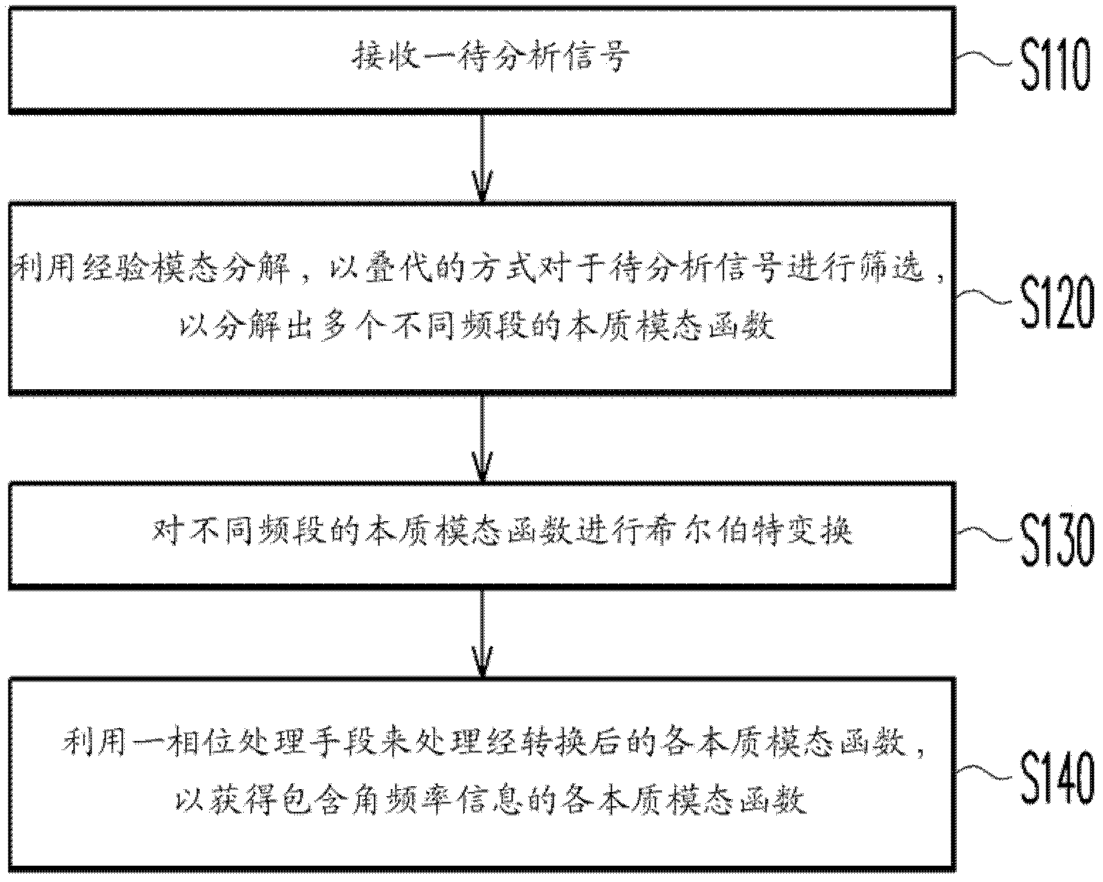
[0029] figure 1 A flowchart showing the steps of the signal analysis method according to the embodiment of the present invention. Please refer to figure 1 , the signal analysis method of this embodiment processes the signal in the time domain to obtain time-varying frequency information. First, in step S110, a signal to be analyzed is received. The signal to be analyzed includes, for example, a slow time axis signal reflected by the substance to be detected in the region to be detected, which includes Doppler shift information. Next, in step S120, the signal to be analyzed is screened iteratively by using empirical mode decomposition, so as to decompose a plurality of essential mode functions of different frequency bands. For the empirical mode decomposition method, reference may be made to documents such as US20100092028A1 and US6901353B1, but not limited thereto. The result of decomposition in this step includes at least one essential mode function. In an embodiment, if...


PUM


Abstract

A time domain signal analysis method is provided. The signal analysis method includes the following steps. A signal to be analyzed is received. The signal to be analyzed is iteratively sifted by using Empirical Mode Decomposition (EMD) to extract at least one intrinsic function (IMF). A normalized Hilbert transform is performed on the IMF. The transformed IMF includes phase information. The transformed IMF is processed by means of phase processing to obtain the processed IMF including angular frequency information. The foregoing signal analysis method could be utilized in an ultrasound imaging system to identify image information of ultrasound images.

Description

technical field [0001] The invention relates to a signal analysis method, and in particular to an analysis method of an ultrasonic image signal and its application. Background technique [0002] In the known technology, ultrasonic imaging has been widely used in various fields, such as industry, military, medicine, etc. in various fields. Among them, the ultrasonic imaging system can be used to measure the physiological characteristics of human tissues, such as the flow velocity of blood vessels or blood, etc. in medical applications. It uses Doppler (Doppler) principle to transmit ultrasonic energy to the human tissue area to be measured, and then receives the ultrasonic energy value reflected by the area to be measured. According to the reflected ultrasonic energy, the ultrasonic imaging system can display a two-dimensional ultrasonic image of the area to be tested. However, for detecting the low flow rate of blood in the blood vessel or the small diameter of the blood v...

Claims


Application Information

Patent Timeline
IPC IPC(8): A61B8/00A61B8/06
CPCA61B8/06A61B8/488A61B8/5223G16H50/30
Inventor 李皇德邵耀华张幼青黄百纲施明
Owner IND TECH RES INST
Why Eureka
Try Eureka