Angle steel punching positioning device, angle steel punching equipment and angle steel positioning punching method

A technology of positioning device and hole position, which is applied in the direction of positioning device, feeding device, storage device, etc., can solve the problems of many preparations, lower punching efficiency, cumbersome positioning of angle steel punching, etc., to achieve a simple positioning method and improve production. The effect of efficiency

Inactive Publication Date: 2016-03-30
青岛富轩电力科技有限公司
View PDF4 Cites 0 Cited by
  • Summary
  • Abstract
  • Description
  • Claims
  • Application Information

AI Technical Summary

Problems solved by technology

[0002] The traditional angle steel positioning device is realized by positioning frame, positioning block and positioning hole. This method requires a large number of positioning blocks, resulting in more preparation work before punching. In addition, the punching of one specification of angle steel needs to be positioned once. , so that the punching positioning of the angle steel becomes cumbersome, and the punching efficiency is also reduced

Method used


Image

  • Angle steel punching positioning device, angle steel punching equipment and angle steel positioning punching method
  • Angle steel punching positioning device, angle steel punching equipment and angle steel positioning punching method

Examples


Embodiment 1

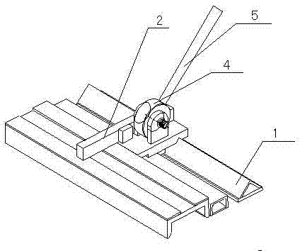
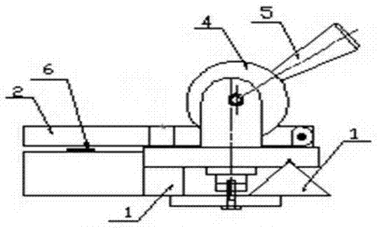
[0024] The angle steel punching device of the present invention comprises a guide rail 1, a baffle plate 2 and a clamping device, the baffle plate 2 and the clamping device are arranged on the guide rail 1 and can slide along the guide rail 1, and the clamping device is used to fix the position of the baffle plate 2, The baffle plate 2 and the clamping device are arranged coaxially, and the baffle plate 2 can rotate along the axis to a position extending laterally above the angle steel seat. The clamping device includes an eccentric wheel 4 and a handle 5, the handle 5 is fixed on the eccentric wheel 4, and the action of the handle 5 drives the eccentric wheel 4 to move.

Embodiment 2

[0026] The technical scheme of the angle steel punching equipment of the present invention is such: it comprises angle steel base, punching device, and angle steel is dragged along angle steel base to carry out punching, and steel plate ruler 6 is set on the angle steel base, and it also comprises angle steel punching positioning device, The number of angle steel punching and positioning devices corresponds to the number of punching holes. The angle steel punching and positioning device is arranged on the inner side of the angle steel seat, which includes guide rail 1, baffle plate 2 and clamping device. The baffle plate 2 and clamping device are arranged on the The guide rail 1 can slide along the guide rail 1. The clamping device is used to fix the position of the baffle 2. The baffle 2 and the clamping device are coaxially arranged. The baffle 2 can be rotated along the axis to extend laterally above the angle steel seat. . The clamping device includes an eccentric wheel 4 ...


PUM


Abstract

The invention relates to post treatment equipment and method for angle steel, in particular to angle steel punched hole positioning device, angle steel punching equipment and an angle steel positioning and punching method. According to the angle steel punched hole positioning device, the angle steel punching equipment and the angle steel positioning and punching method, which are provided by the invention, a plurality of positioning devices are arranged on guide rails and can position each hole on angle steel. The angle steel punching equipment comprises an angle steel seat, a punching device and the angle steel punched hole positioning device, the angle steel performs punching by dragging the angle steel along the angle steel seat, and a steel ruler is arranged on the angle steel seat; the number of the angle steel punched hole positioning devices is equal to that of punched holes; the angle steel punched hole positioning devices are arranged on the inner side of the angel steel seat; each angle steel punched hole positioning device comprises a guide rail, a baffle and a clamping device, wherein the baffles and the clamping devices are arranged on the guide rails and can glide along the guide rails; the clamping devices are used for fixing the positions of the baffles; the baffles and the clamping devices are coaxially arranged; the baffles can be rotated to the position above the angle steel seat, where the baffles are horizontally extended out, along the axes of the baffles; and the clamping device disclosed by the technical scheme comprises an eccentric wheel and a handle, the handle is fixed on the eccentric wheel and drives the eccentric wheel to move, and the clamping manner is simpler, more convenient and extremely easy to adjust.

Description

technical field [0001] The invention relates to a post-processing equipment and method for angle steel, in particular to an angle steel punching and positioning device, angle steel punching equipment and an angle steel positioning and punching method. Background technique [0002] The traditional angle steel positioning device is realized by positioning frame, positioning block and positioning hole. This method requires a large number of positioning blocks, resulting in more preparation work before punching. In addition, the punching of one specification of angle steel needs to be positioned once. , so that the punching positioning of the angle steel becomes cumbersome, and the efficiency of punching is also reduced. Contents of the invention [0003] In view of the above-mentioned defects, the present invention provides an angle steel punching positioning device, an angle steel punching equipment and an angle steel positioning and punching method with a plurality of posit...

Claims


Application Information

Patent Timeline
Patent Type & Authority Patents(China)
IPC IPC(8): B21D43/00B21D28/24
Inventor 刘家园
Owner 青岛富轩电力科技有限公司
Why Eureka
Try Eureka