centrifugal fan

A technology of centrifugal blades and blades, which is applied to parts of pumping devices for elastic fluids, non-variable pumps, machines/engines, etc., which can solve the problem of not many centrifugal blades and achieve good static pressure values , increase the air intake area, and eliminate the effect of noise peaks

Active Publication Date: 2015-09-16
NINGBO LANGDI IMPELLER MACHINERY
View PDF7 Cites 0 Cited by
  • Summary
  • Abstract
  • Description
  • Claims
  • Application Information

AI Technical Summary

Problems solved by technology

At present, there are not many centrifugal fan blades with reasonable air volume and noise control in the market

Method used


Image

  • centrifugal fan
  • centrifugal fan
  • centrifugal fan

Examples


Embodiment Construction

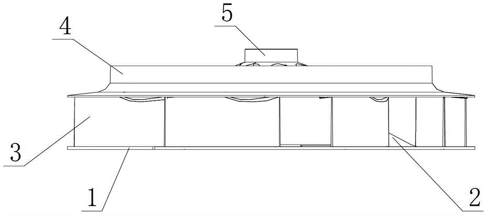
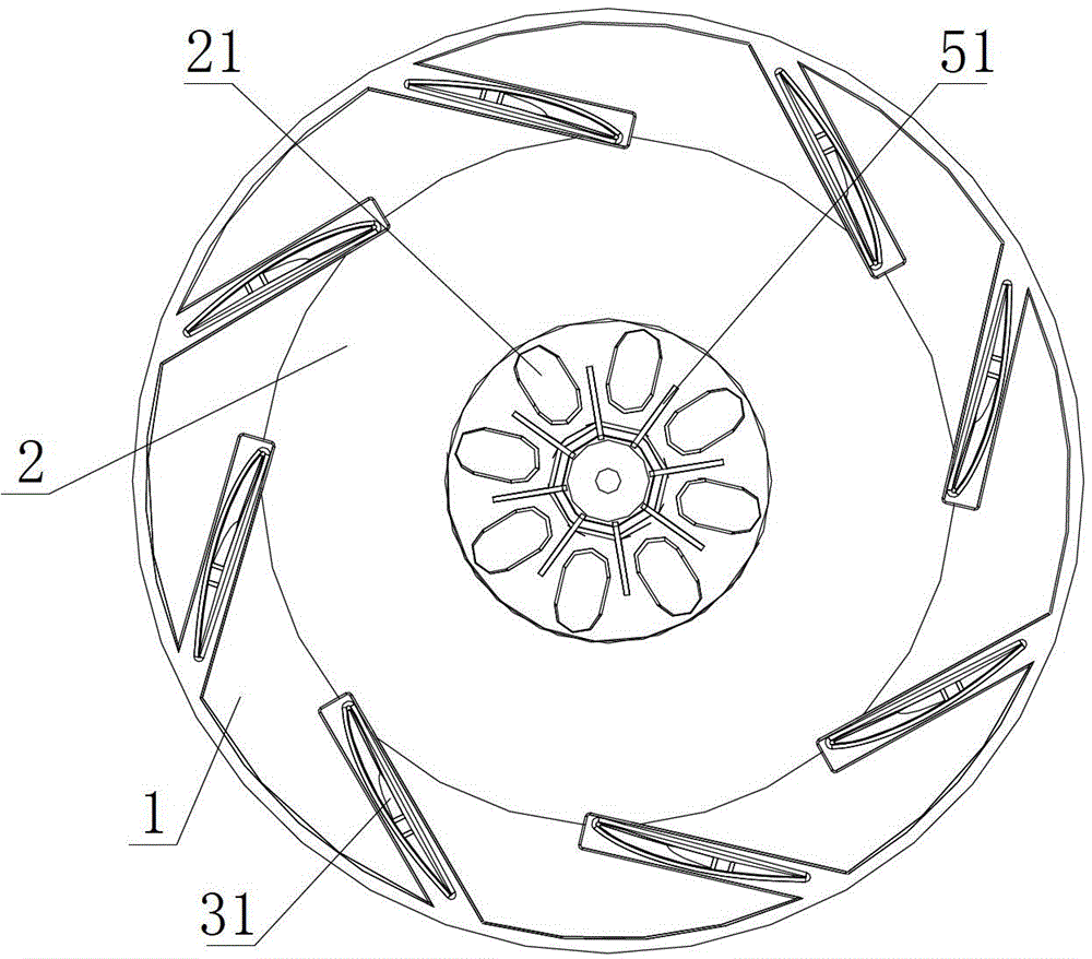
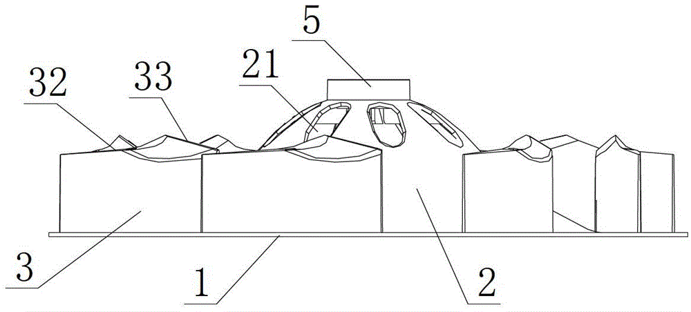
[0016] Combine below figure 1 , figure 2 , image 3 with Figure 4 Make a detailed explanation to the specific embodiment of the invention.

[0017] Such as figure 1 , figure 2 , image 3 with Figure 4 The centrifugal fan blade shown mainly includes an annular leaf base plate 1, a hub 2, blades 3 and a guide ring 4, the blades 3 are 8 pieces, and the 8 blades 3 are vertically arranged on the annular leaf base plate 1 and the guide ring 4, the hub 2 is integrated with the inner side of the annular leaf base plate 1, the hub 2 is concentric with the annular leaf base plate 1, and the center of the top of the hub 2 is provided with a cylindrical plastic shaft hole sleeve 5 connected with it. A material-saving cavity 31 is set inside the blade 3, and eight cooling holes 21 are arranged on the hub 2, and the eight cooling holes 21 are arranged at regular intervals, and each cooling hole 21 is located from the outer air outlet end of the blade 3 to the ring-shaped blade. ...


PUM


Abstract

The invention relates to the field of ventilating equipment. A centrifugal fan vane comprises a circular blade base board, a hub, blades and a deflector ring, wherein the deflector ring protrudes from the top end of the hub; the number of the blades is eight, and the eight blades are perpendicularly arranged between the circular blade bottom board and the deflector ring; the air intake angle is not larger than 10 degrees, and the air exit angle is between 25-35 degrees; the blade axis angles between adjacent blades are different; and the upper part of each blade is composed of a connecting section and a non-connecting section which are connected into a whole, and the length of the connecting section accounts for 68-72% of the length of the top of the blade. The centrifugal fan vane has the advantages of novel structure, large air flow and low noise.

Description

technical field [0001] The invention relates to the field of ventilation equipment, in particular to a centrifugal fan blade. Background technique [0002] The centrifugal fan blade is a commonly used product in the field of ventilation equipment. The centrifugal fan blade includes a circular leaf base plate, a hub, a blade and a guide ring. The blade is fixed between the circular leaf base plate and the guide ring. The hub and the circular ring The inner side of the blade bottom plate is connected as a whole, the hub and the annular blade bottom plate are concentric, and a shaft sleeve is arranged at the center of the hub top. When in use, the motor shaft passes through the shaft hole on the shaft sleeve to drive the fan blade to rotate. The performance of the centrifugal fan blade is mainly reflected in the air volume and noise control. The air volume and the noise level are interrelated. Generally, the noise is relatively high when the air volume is large, and the noise i...

Claims


Application Information

Patent Timeline
Patent Type & Authority Patents(China)
IPC IPC(8): F04D29/28F04D29/30
Inventor 高文铭韩小红施建立
Owner NINGBO LANGDI IMPELLER MACHINERY
Why Eureka
Try Eureka