Integral reactor with top double-layer structure

A double-layer structure, reactor technology, applied in general reactors, non-uniform reactors, reactors, etc., can solve problems such as poor project implementation, inconvenient in-service inspection and maintenance of equipment, and poor equipment reliability, and achieve high safety, The effect of good project implementation and easy maintenance

Active Publication Date: 2013-07-03
SHANGHAI NUCLEAR ENG RES & DESIGN INST CO LTD
View PDF6 Cites 11 Cited by
  • Summary
  • Abstract
  • Description
  • Claims
  • Application Information

AI Technical Summary

Problems solved by technology

On the one hand, various main pumps and control rod drive mechanisms in the prior art cannot meet the requirements of such harsh working conditions, so the engineering implementation of the design is poor; Among the agents, the reliability of the equipment is poor, and the inspection and maintenance of the equipment in service are inconvenient

Method used


Image

  • Integral reactor with top double-layer structure
  • Integral reactor with top double-layer structure
  • Integral reactor with top double-layer structure

Examples


Embodiment 1

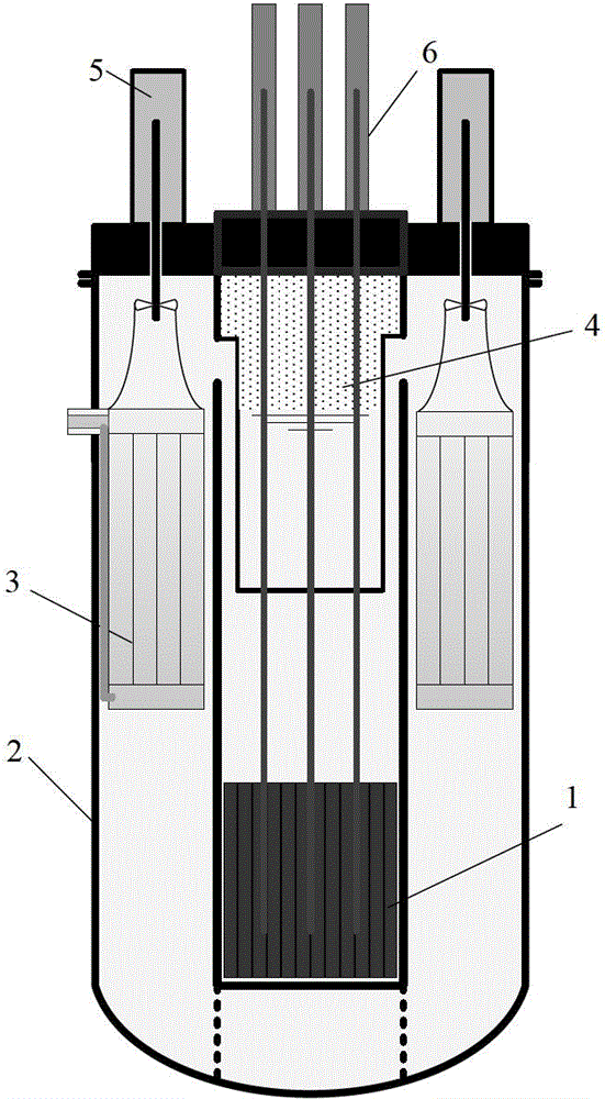
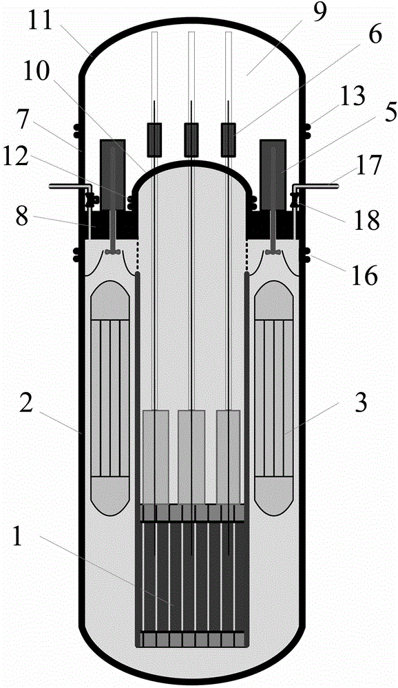
[0035] like image 3 As shown, in the integrated reactor with a double-layer structure on the top of the present invention, the reactor core 1, built-in steam generator 3, main pump 5, control rod drive mechanism 6 and other equipment are all installed in the pressure vessel 2 Inside.

[0036] Wherein, the core 1 and the built-in steam generator 3 are arranged under the equipment supporting platform 8 .

[0037]The upper cylinder body 7 of the pressure vessel and the ring-shaped equipment support platform 8 form an integral structure, and the arc-shaped pressure vessel inner top cover 10 is connected to the through hole in the center of the equipment support platform 8 through the pressure vessel inner top cover and the flange 12 of the equipment support platform edge. The control rod driving mechanism 6 is arranged above the inner top cover 10 of the pressure vessel, and the driving line of the control rod assembly passes through the inner top cover 10 of the pressure vesse...

Embodiment 2

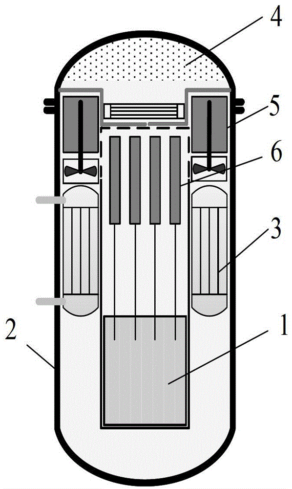
[0045] like Figure 6 As shown, another integrated reactor with a double-layer structure on the top of the present invention, its core 1, built-in steam generator 3, main pump 5, control rod drive mechanism 6 and other major equipment are directly installed on the pressure Inside container 2.

[0046] Wherein, the core 1 and the built-in steam generator 3 are arranged under the flat roof 19 .

[0047] The upper cylinder body 7 of the pressure vessel and the flat top cover 19 form an integral structure, and the flat top cover 19 doubles as an equipment support platform. The upper flange 16 of the pressure vessel is arranged on the cylindrical body below the flat top cover 19 to facilitate the disassembly of the flat top cover 19 . The main pump 5 and the control rod driving mechanism 6 are arranged on the flat top cover 19 , and the driving line of the main pump shaft, the impeller and the control rod assembly passes through the flat top cover 19 .

[0048] The pressure vess...


PUM


Abstract

The invention provides an integral reactor with a double-layer structure at the top, which comprises a reactor core arranged in a pressure vessel, a built-in steam generator, a main pump and a control rod drive mechanism. A pressure vessel upper cylinder and a ring-shaped equipment support platform form an integral structure, and an arc-shaped pressure vessel inner top cover is connected to the equipment support platform through a flange of the pressure vessel inner top cover and the equipment support platform; the control rod drive mechanism is arranged on the pressure vessel inner top cover, and the main pump is arranged on the equipment support platform; the reactor core and the built-in steam generator are arranged below the equipment support platform; and a pressure vessel outer top cover is arranged at the top end of the cylinder which is arranged at the upper part of the pressure vessel, and is connected with the pressure vessel upper cylinder through a flange of the pressure vessel outer top cover and the pressure vessel upper cylinder. The invention is a structural design solution to the integral reactor having higher safety and better construction property.

Description

technical field [0001] The invention relates to the design of a novel nuclear reactor, in particular to an integrated reactor form with a double-layer structure on the top. Background technique [0002] The integrated reactor is different from the conventional loop reactor in that the steam generator, main pump, control rod drive mechanism and other main equipment are directly combined with the pressure vessel as a whole, so that the structure of the main coolant system of the reactor is more compact, which is beneficial to Miniaturization of nuclear reactors; due to the removal of connecting pipes between these devices, the frequency of breach accidents is reduced, which is conducive to improving the safety of nuclear reactors. [0003] International and domestic R&D institutions have proposed various forms of integrated reactors, including the IRIS reactor developed by Westinghouse Corporation of the United States, the SMART reactor developed by the Korea Atomic Energy Res...

Claims


Application Information

Patent Timeline
Patent Type & Authority Applications(China)
IPC IPC(8): G21C13/02G21C13/10G21C1/32
CPCY02E30/30
Inventor 林千司胜义廖亮申屠军
Owner SHANGHAI NUCLEAR ENG RES & DESIGN INST CO LTD
Why Eureka
Try Eureka