Electric wiring protection device

A protection device and electrical wiring technology, applied in circuit devices, emergency protection circuit devices, emergency protection devices with automatic disconnection, etc. Reliability, the effect of improving the detection function

Active Publication Date: 2013-07-03
浙江益而益智能科技有限公司
View PDF3 Cites 0 Cited by
  • Summary
  • Abstract
  • Description
  • Claims
  • Application Information

AI Technical Summary

Problems solved by technology

[0004] The disadvantage of the first type of method is that since a current transformer is used to detect the residual current in the phase, zero and ground wires at the same time, for example, when there is residual current in the phase, zero, and ground wires at the same time, the phase and neutral wires The detection of the residual current in the ground wire and the detection of the residual current in the ground wire will interfere with each other, posing a safety hazard
[0005] Although the second type uses separate current transformers, since the signal feedback and / or control loops of the two separate current transformers have a common functional module, the two current transformers cannot actually work completely independently. For example, when a shared functional module such as an amplifying circuit fails, neither of the two current transformers will be able to detect residual current. The complexity also increases the cost of

Method used


Image

  • Electric wiring protection device

Examples


Embodiment Construction

[0024] While the following text sets forth a detailed description of various embodiments of the invention, it should be understood that the legal scope of the invention is defined by the words of the claims appended hereto. The detailed description should be construed as exemplary only and not describing every possible embodiment of the invention since describing every possible embodiment would be impractical, if not impossible. Various alternative embodiments could be implemented, using either current technology or technology developed after the filing date of this patent, which would still fall within the scope of the claims defining the invention.

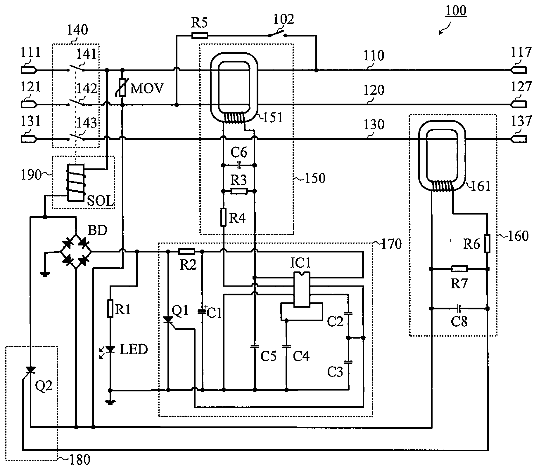
[0025] figure 1 A circuit diagram of an electrical connection protection device 100 according to an embodiment of the present invention is shown. As shown in the figure, the electrical connection protection device 100 includes: a phase conductor 110, a neutral conductor 120, a ground conductor 130, a switch device 140, a first ...


PUM


Abstract

The invention relates to an electric wiring protection device which comprises a phase line conductor, a null line conductor, a ground wire conductor, a switching device, a rectifier bridge, a first residual current detection circuit, a second residual current detection circuit, a signal processing circuit, a signal driving circuit and an excitation device, wherein the first residual current detection circuit detects the residual current of the phase line conductor and the null line conductor; the second residual current detection circuit detects the residual current of the ground wire conductor; and the signal processing circuit and the signal driving circuit can independently generate a first driving signal and a second driving signal. According to the device, the detection of the residual current of the phase line conductor and the null line conductor and the detection of the residual current of the ground wire conductor are independently performed, so that the detection reliability and the safety of the device are improved.

Description

technical field [0001] The invention relates to the field of electric safety protection, in particular to an electric connection protection device with a breaking characteristic between an input end and an output end. Background technique [0002] Due to the non-standard wiring of users, there may be wrong wiring in the power socket of household appliances, such as cross-connecting the phase wire and neutral wire of the socket, or connecting the ground wire to the phase wire, which will easily cause the insulation performance of the electrical appliance shell to decrease or Charged, resulting in electric shock accidents. [0003] Existing residual current protection devices with the function of detecting the wiring status of power sockets generally have two types: the first type uses a current transformer to simultaneously detect the residual current in the phase, zero, and ground wires; the second type In order to use two current transformers, that is, one of the current t...

Claims


Application Information

Patent Timeline
Patent Type & Authority Applications(China)
IPC IPC(8): H02H3/32
Inventor 岳国兰李成力
Owner 浙江益而益智能科技有限公司
Why Eureka
Try Eureka