
Method for improving circuit voltage by adopting core controller and taking input voltage as reference

A core controller and input voltage technology, applied in circuit devices, AC network voltage adjustment, electrical components, etc., can solve the problems of system voltage collapse, inconvenient practical application, etc., to improve voltage, increase cost investment, and improve use value. Effect

Inactive Publication Date: 2013-07-03
FUJIAN YANGGU INTELLIGENT TECH
View PDF6 Cites 5 Cited by
  • Summary
  • Abstract
  • Description
  • Claims
  • Application Information

AI Technical Summary

Problems solved by technology

Since the voltage regulating transformer cannot change the balance state of reactive power demand, if the reactive power shortage is large, in order to maintain the voltage level, the on-load voltage regulating transformer operates, and the voltage rises temporarily, and all the reactive power shortage is transferred to the main network, thereby Make the main grid voltage drop gradually, which may lead to system voltage collapse in severe cases
However, if it is an off-load voltage regulating transformer, it needs to be powered off, which is inconvenient for practical application.

Method used

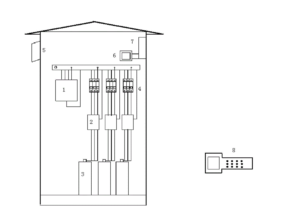
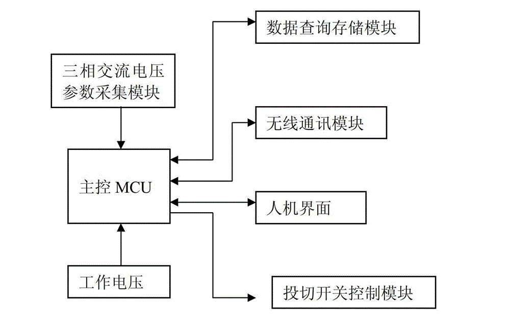

Image

  • Method for improving circuit voltage by adopting core controller and taking input voltage as reference
  • Method for improving circuit voltage by adopting core controller and taking input voltage as reference
  • Method for improving circuit voltage by adopting core controller and taking input voltage as reference

Examples


Embodiment Construction

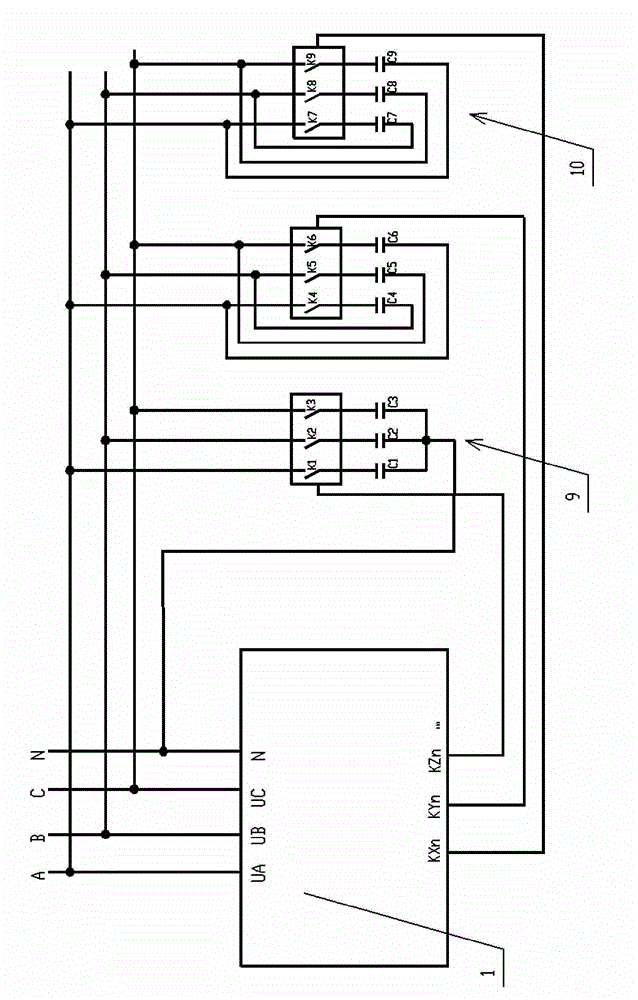
[0023] The core controller wiring diagram, working principle and working process of the present invention will be described in detail below in conjunction with the accompanying drawings and embodiments:

[0024] Such as figure 1 As shown, the core controller wiring schematic diagram of the present invention, the principle of the invention basis of the present invention is: its core controller 1 collects A, B, C three-phase AC voltage and parameters, and the collected data is analyzed by the core controller At the same time, the core controller sends control instructions to the switching switch control module according to the analysis and calculation results to make the corresponding compound switch act to adjust the corresponding star-connected capacitors and delta-connected capacitors. Among them, the star-connected capacitor controls the switching action of the capacitor according to the principle of the influence of the reactive power balance on the voltage in the power sys...


PUM


Abstract

The invention discloses a method for improving circuit voltage by adopting a core controller and taking an input voltage as a reference. The core controller and a compound switch are adopted by the method disclosed by the invention; the method is characterized by comprising the following steps of: analyzing and calculating via the core controller according to a collected three-phase alternating voltage and a parameter; simultaneously sending a control command to a switch control module according to analyzing and calculating results and enabling the corresponding compound switch to act so as to adjust the investment of capacitors; controlling and reducing the investment of the capacitors by the core controller when the value of a reactive power output by the reactive power supply is greater than the value of a reactive load and the value of the loss in the network; controlling and increasing the investment of the capacitors by the core controller when the value of the reactive power output by the reactive power supply is less than the value of the reactive load and the value of the loss in the network; and controlling the capacitors to maintain the state and not change the state by the core controller when the value of the reactive power output by the reactive power supply is balanced or basically balanced with the value of the reactive load and the value of the loss in the network. By adopting the method disclosed by the invention, the automatic tracking of the input voltage change is realized and the reasonable adjustment of the voltage of branched wires is realized.

Description

[0001] The patent application of the present invention is a divisional application for the patent application with the filing date of 2011.01.21, the application number of 201110023220.2, and the title of the invention "branch line voltage regulator with voltage-based controller and composite switch". technical field [0002] The invention relates to the field of a branch line voltage regulating device, in particular to a method for improving line voltage by using a core controller with an input voltage as a reference. Background technique [0003] For power companies, loss reduction, energy saving and improvement of power quality are the goals that have been pursued. Due to the characteristics of long lines, large line losses, wide load distribution, and many branch lines in rural power grids, the power load varies greatly with day and night and seasons, especially in some remote areas, there are a certain number of long-distance branch lines whose power supply radius exceed...

Claims


Application Information

Patent Timeline
IPC IPC(8): H02J3/16H02J13/00
CPCY02E40/30Y02E40/70Y02E60/00Y04S10/00Y04S10/22
Inventor 傅谦易智勇余辉生
Owner FUJIAN YANGGU INTELLIGENT TECH
Learn More