Large numerical control floor type boring and milling machine ram deflection compensating device

A compensation device, milling and boring machine technology, applied in other manufacturing equipment/tools, manufacturing tools, etc., can solve problems such as downward deflection, and achieve the effect of easy debugging and low investment cost

Inactive Publication Date: 2012-04-04
SHENJI GRP KUNMING MACHINE TOOL
View PDF6 Cites 8 Cited by
  • Summary
  • Abstract
  • Description
  • Claims
  • Application Information

AI Technical Summary

Problems solved by technology

[0003] The purpose of the present invention is to overcome the problem of downward deflection of the existing large-scale CNC floor milling and boring machine ram extending from the spindle box, and to invent a large-scale CNC floor milling and boring machine ram deflection compensation device, which can compensate for the ram deflection caused by the ram. After extending the spindle box, the ram deflection caused by the deformation of the guide rail pair of the ram and the spindle box due to the change of the center of gravity, and let the ram reach the predetermined control accuracy, so as to ensure the machining accuracy of the machine tool

Method used


Image

  • Large numerical control floor type boring and milling machine ram deflection compensating device
  • Large numerical control floor type boring and milling machine ram deflection compensating device
  • Large numerical control floor type boring and milling machine ram deflection compensating device

Examples


Embodiment Construction

[0010] The present invention will be described in further detail below in conjunction with the accompanying drawings.

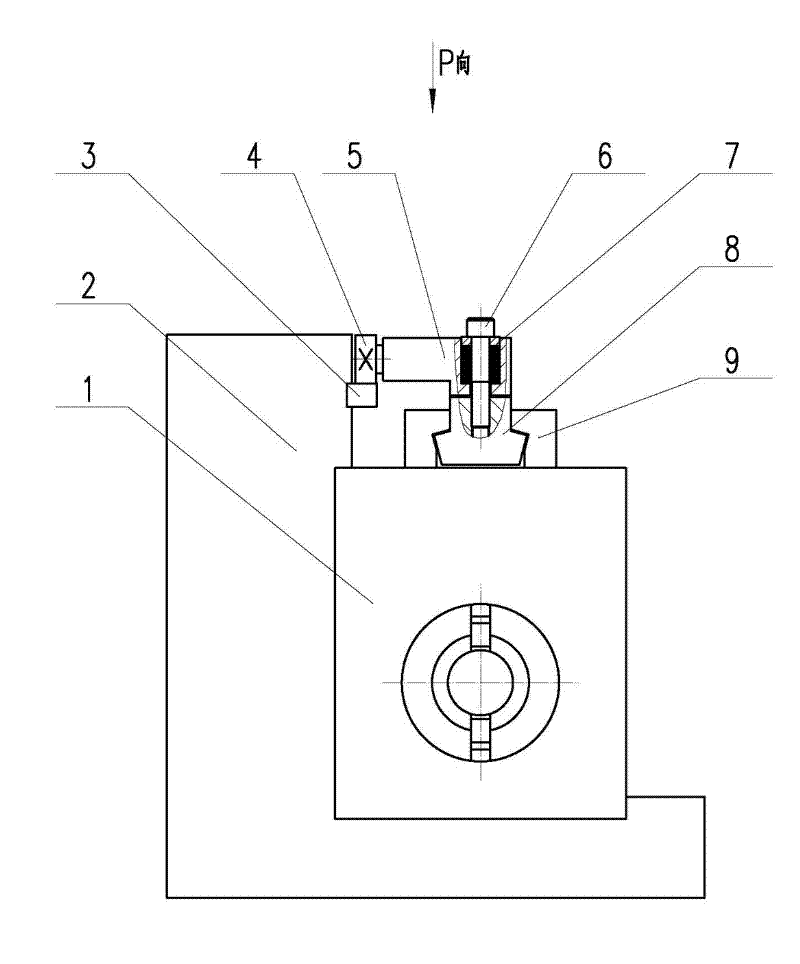
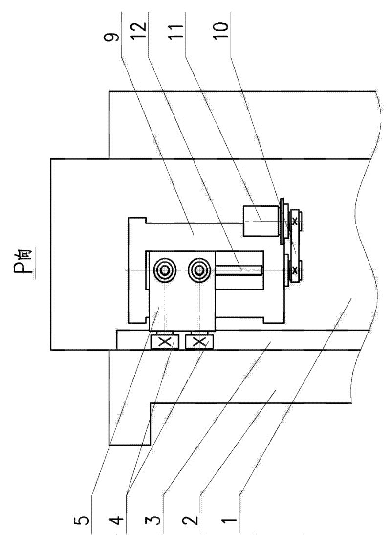
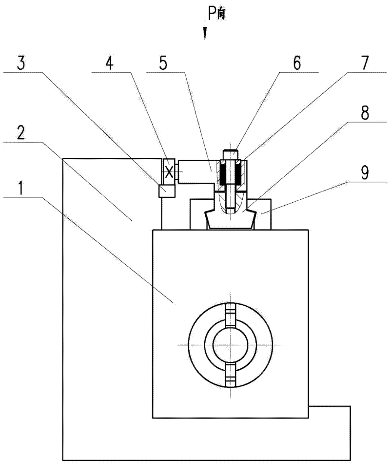
[0011] Ram deflection compensation device for large-scale CNC floor milling and boring machine, including guide rail 3, roller 4, connecting seat 5, spring 7, slider 8, pressure plate 9, belt transmission mechanism 10, motor 11, screw pair 12, guide rail 3 is installed horizontally on On the headstock 2, the pressure plate 9 is installed on the ram 1, the roller 4 is installed on the connecting seat 5 and rolls with the guide rail 3, and the contact force between the roller 4 and the guide rail 1 is guaranteed by the compression of the spring 7. One end of the lead screw pair is installed on the pressure plate, and the other end is installed on the slider, and the connecting seat and the slider are connected into one body through screws and springs. After the ram extends out of the headstock, the ram becomes a cantilever beam, and the self-weight causes the d...


PUM


Abstract

The invention relates to a large numerical control floor type boring and milling machine ram deflection compensating device, which belongs to the field of mechanical equipment, and comprises a guide rail (3) arranged on a spindle box (2), a pressing plate (9) arranged on a ram (1), and an idler wheel (4) arranged on a connecting seat (5) and matched with the guide rail (3) in a rolling way. One end of a screwpair (12) is arranged on the pressing plate (9), the other end of the screwpair (12) is arranged on a slide block (8), and the connecting seat (5) is connected with the slide block (8) into a whole through a screw (6) and a spring (7). When the ram (1) is stretched out and drawn back, the pressing plate (9) and the slide block (8) drive the idler wheel (4) to move along the guide rail(3). The device has the characteristics of simplicity and convenience in installing and debugging, compensation dosage adjustment in time, and the like, so that the device is economical and practical, and has low investment cost and high promotional value.

Description

technical field [0001] The invention relates to a ram deflection compensation device for a large-scale numerical control floor milling and boring machine, which belongs to the field of mechanical equipment. Background technique [0002] Since the spindle ram of the large-scale CNC floor milling and boring machine protrudes from the headstock into a cantilever state, the forward movement of the center of gravity of the ram deforms the guide rail pair of the ram and the headstock, and finally causes the extended part of the ram to deflect downwards. produce deflection. In this case, if an accessory is installed at the front of the ram, the deflection of the ram will increase. Therefore, the deflection error generated after the ram extends out of the headstock will directly affect the geometric accuracy and machining accuracy of the machine tool. Contents of the invention [0003] The purpose of the present invention is to overcome the problem of downward deflection of the ...

Claims


Application Information

Patent Timeline
Patent Type & Authority Applications(China)
IPC IPC(8): B23Q23/00
Inventor 王全宝高丽明陶骏李军张力柴会敏王自强
Owner SHENJI GRP KUNMING MACHINE TOOL
Why Eureka
Try Eureka