Multi-cylinder rotary compressor and refrigeration cycle device

A rotary compressor and multi-cylinder technology, which is applied to rotary piston machines, rotary piston pumps, rotary piston/oscillating piston pump components, etc., can solve problems such as reducing compression work

Active Publication Date: 2013-07-03
TOSHIBA CARRIER CORP
View PDF8 Cites 6 Cited by
  • Summary
  • Abstract
  • Description
  • Claims
  • Application Information

AI Technical Summary

Problems solved by technology

In such a compressor, it would be very advantageous if it could be switched between full capacity operation and half capacity operation in which compression is performed simultaneously in a plurality of cylinder chambers. In the operation with the capacity halved, the compression is performed in one cylinder chamber and the compression is stopped in the other cylinder chamber, thereby reducing the compression work.

Method used


Image

  • Multi-cylinder rotary compressor and refrigeration cycle device
  • Multi-cylinder rotary compressor and refrigeration cycle device
  • Multi-cylinder rotary compressor and refrigeration cycle device

Examples


Embodiment Construction

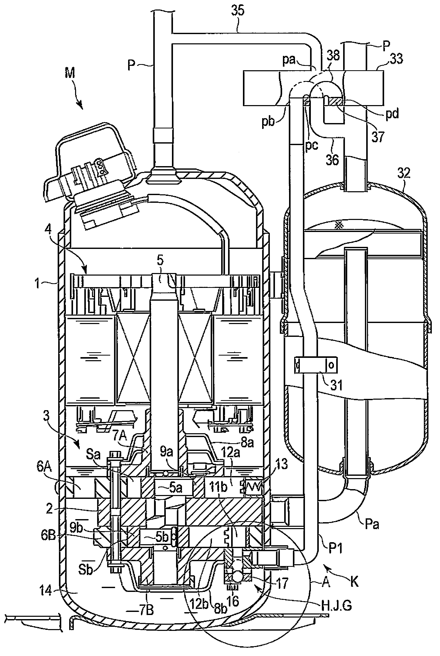
[0020] Hereinafter, this embodiment will be described based on the drawings. figure 1 It is a schematic longitudinal sectional view of the multi-cylinder rotary compressor M of this embodiment. Reference numeral 1 in the figure is an airtight case, and the compression mechanism part 3 is provided in the lower part in this airtight case 1, and the motor part 4 is provided in the upper part. The motor unit 4 and the compression mechanism unit 3 are integrally connected via a rotating shaft 5 .

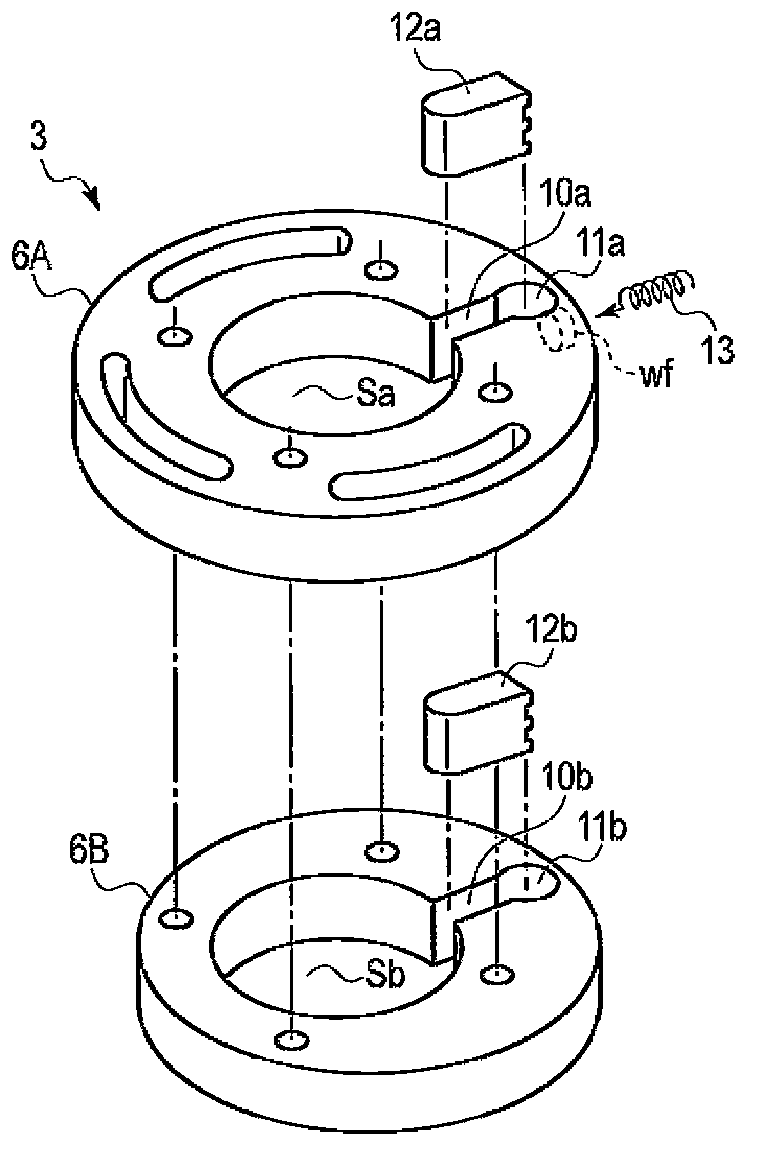
[0021] The compression mechanism unit 3 includes a first cylinder 6A on the upper side and a second cylinder 6B on the lower side. A main bearing 7A is fixed to the upper end surface of the first cylinder 6A, and a sub-bearing 7B is fixed to the lower end surface of the second cylinder 6B. The intermediate partition plate 2 is interposed between the first cylinder 6A and the second cylinder 6B.

[0022] The above-mentioned rotary shaft 5 penetrates the inside of each cylinder 6A, 6B, ...


PUM


Abstract

In a multi-cylinder rotary compressor (M), a compression mechanism (3) interconnects a back-pressure introduction pathway (H) to a blade back chamber (11b) that movably houses the back end of a second blade (12b). A check valve mechanism (G) is provided to a lubricating oil interconnection path (J) that interconnects the blade back chamber (11b) and an oil sump (14). When high pressure is introduced from the back-pressure introduction pathway (H) to the blade back chamber (11b), the lubricating oil interconnection path (J) opens, and when low pressure is introduced to the blade back chamber (11b), the lubricating oil interconnection path (J) closes. The back-pressure introduction pathway (H) and the lubricating oil interconnection path (J) are configured in a manner such that the amount of fluid flowing in from the back-pressure introduction pathway (H) to the blade back chamber (11b) when high pressure is introduced to the blade back chamber (11b) and the second blade (12b) moves in the direction that expands the volume of the blade back chamber (11b) is greater than the amount of fluid flowing out from the blade back chamber (11b) to the back-pressure introduction pathway (H) when the second blade (12b) moves in the direction that reduces the volume of the blade back chamber (11b).

Description

technical field [0001] Embodiments of the present invention relate to a multi-cylinder rotary compressor and a refrigeration cycle device including the multi-cylinder rotary compressor to constitute a refrigeration cycle. Background technique [0002] In a refrigeration cycle apparatus, a multi-cylinder rotary compressor including a plurality of cylinder chambers in a compression mechanism is often used. In such a compressor, it would be very advantageous if it could be switched between full capacity operation and half capacity operation in which compression is performed simultaneously in a plurality of cylinder chambers. In the above-mentioned capacity reduction operation, the compression action is performed in one cylinder chamber, and the compression action is stopped in the other cylinder chamber, thereby reducing the compression work. [0003] The compression mechanism section of the compressor disclosed in Japanese Patent Application Laid-Open No. 2008-520901 includes...

Claims


Application Information

Patent Timeline
Patent Type & Authority Applications(China)
IPC IPC(8): F04C23/00F04C18/356
CPCF04C18/3564F01C21/0863F04C23/001F04C23/008F04C29/128
Inventor 平山卓也M·雅费特费尔德伊
Owner TOSHIBA CARRIER CORP
Why Eureka
Try Eureka