Child's safety seat

A technology for child safety seats and limit devices, which is applied in the field of limit devices, can solve problems such as broken load-bearing structures and unguaranteed safety of child safety seats, and achieve the effect of offsetting deformation

Active Publication Date: 2013-07-10
BRITAX ROMER KINDERSICHERHEIT
View PDF7 Cites 3 Cited by
  • Summary
  • Abstract
  • Description
  • Claims
  • Application Information

AI Technical Summary

Problems solved by technology

Since the thrust is generated in the event of an impact, the deformation force acting on the child safety seat is too strong, so the deformation of the outer cover may cause the problem of breaking the load-bearing structure of the outer cover, and the child safety seat safety is not guaranteed

Method used


Image

  • Child's safety seat
  • Child's safety seat
  • Child's safety seat

Examples


Embodiment Construction

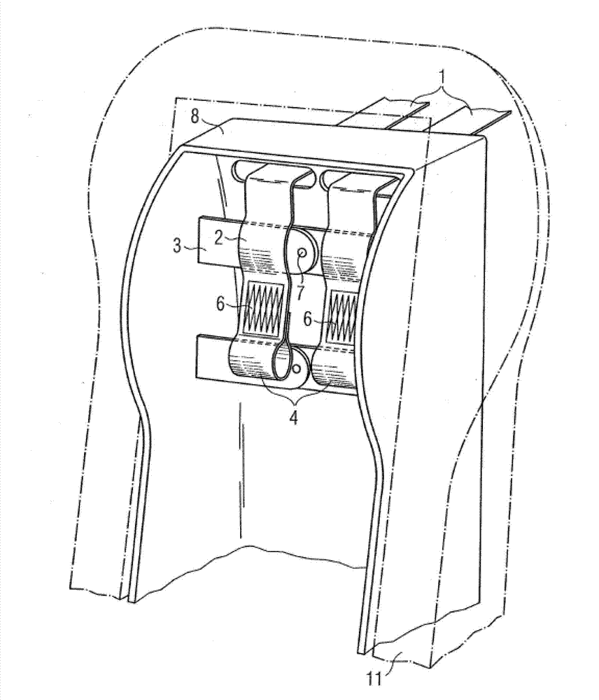
[0031] figure 1 A prior art restraint device is shown, comprising two top tethers 1 guided in a housing 8 mounted in a child safety seat 11 . In the event of an impact, the child safety seat is forced forward as a whole until the crossbar 3 connected to the top tether 1 via the link 2 breaks through the energy absorption area 6 under the wedge effect of the crossbar 3, and finally the child The safety seat stops at the link end of the second link 4.

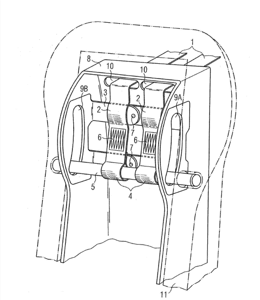
[0032] figure 2 The preferred embodiment of the invention is shown prior to pressing, wherein the top tether 1 is guided in the housing 8 through the opening 10 while the first link 2 is pushed over the crossbar 3 . The top tether 1 further comprises an energy absorbing zone 6 leading to the end of the second link 4 link. The stop assembly 5 arranged on the two radial slits 9A, 9B passes through the second link 4 , wherein the radial slits 9A, 9B are arranged in the outer cover 8 . For ease of assembly, the crossbar 3 may co...


PUM


Abstract

A restraining device according to the invention for a child's safety seat provided to be fixed in a vehicle by at least one top tether, wherein the at least one top tether comprises at least one first loop that is provided to be pushed over a crossbar, is characterised in that the at least one top tether comprises a second loop provided to be pushed over restraining means.

Description

technical field [0001] The invention relates to a restraint device for a child safety seat installed in a vehicle by at least one top tether, wherein the at least one top tether includes at least a first link movable on a cross bar . Background technique [0002] Such seats are already known in the prior art. The purpose of the top tethers in the child safety seat is to reduce or even completely prevent the child safety seat from rotating forward in the event of a frontal or rear impact. Accordingly, the child safety seat comprises at least one top tether adapted for secure connection with the vehicle. To this end, existing vehicles include stops within the vehicle for mounting a top tether by means of hooks. Typically, the top tether is guided under traction from the child safety seat via the headrest rod to the docking point. After installation, the top tethers are biased such that relative movement of the child safety seat in the event of a frontal or back impact is s...

Claims


Application Information

Patent Timeline
Patent Type & Authority Applications(China)
IPC IPC(8): B60N2/26
CPCB60N2/2809B60N2/2884
Inventor 戴维·肖恩·卡林
Owner BRITAX ROMER KINDERSICHERHEIT
Why Eureka
Try Eureka