
Slack preventing device for wire rod wound around spool, and slack preventing method therefore

A wire and spool technology is applied in the field of preventing the slack of the wire wound on the spool, which can solve the problems of the slack of the wire 4, the difficulty in increasing the winding speed, and the difficulty in quickly exporting the wire, and achieve the effect of preventing slack.

Active Publication Date: 2013-07-10
NITTOKU ENG CO LTD
View PDF6 Cites 21 Cited by
  • Summary
  • Abstract
  • Description
  • Claims
  • Application Information

AI Technical Summary

Problems solved by technology

Therefore, even in the wire rod deriving machine 1, there is a disadvantage that the deriving and stopping operations of the wire 4 are repeated alternately, so that the winding speed of the winding machine is substantially determined by the derivation of the wire 4 of the wire deriving machine 1. Speed, in the case of rotating a large bobbin 2, it becomes difficult to quickly lead out the wire because of its inertia, making it difficult to increase the winding speed
[0007] In order to solve this problem, although it is conceivable to make a lot of wires 4 lead out in advance, there is a disadvantage that if the wires 4 are held in the lead out state, the drawn out wires 4 will return to the bobbin due to their elasticity. 2 side, so that the wire 4 wound on the bobbin 2 will loosen on the bobbin 2

Method used


Image

  • Slack preventing device for wire rod wound around spool, and slack preventing method therefore
  • Slack preventing device for wire rod wound around spool, and slack preventing method therefore
  • Slack preventing device for wire rod wound around spool, and slack preventing method therefore

Examples


Embodiment Construction

[0022] Next, the form for implementing this invention is demonstrated in detail based on drawing.

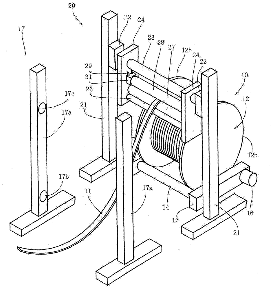
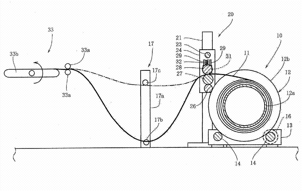
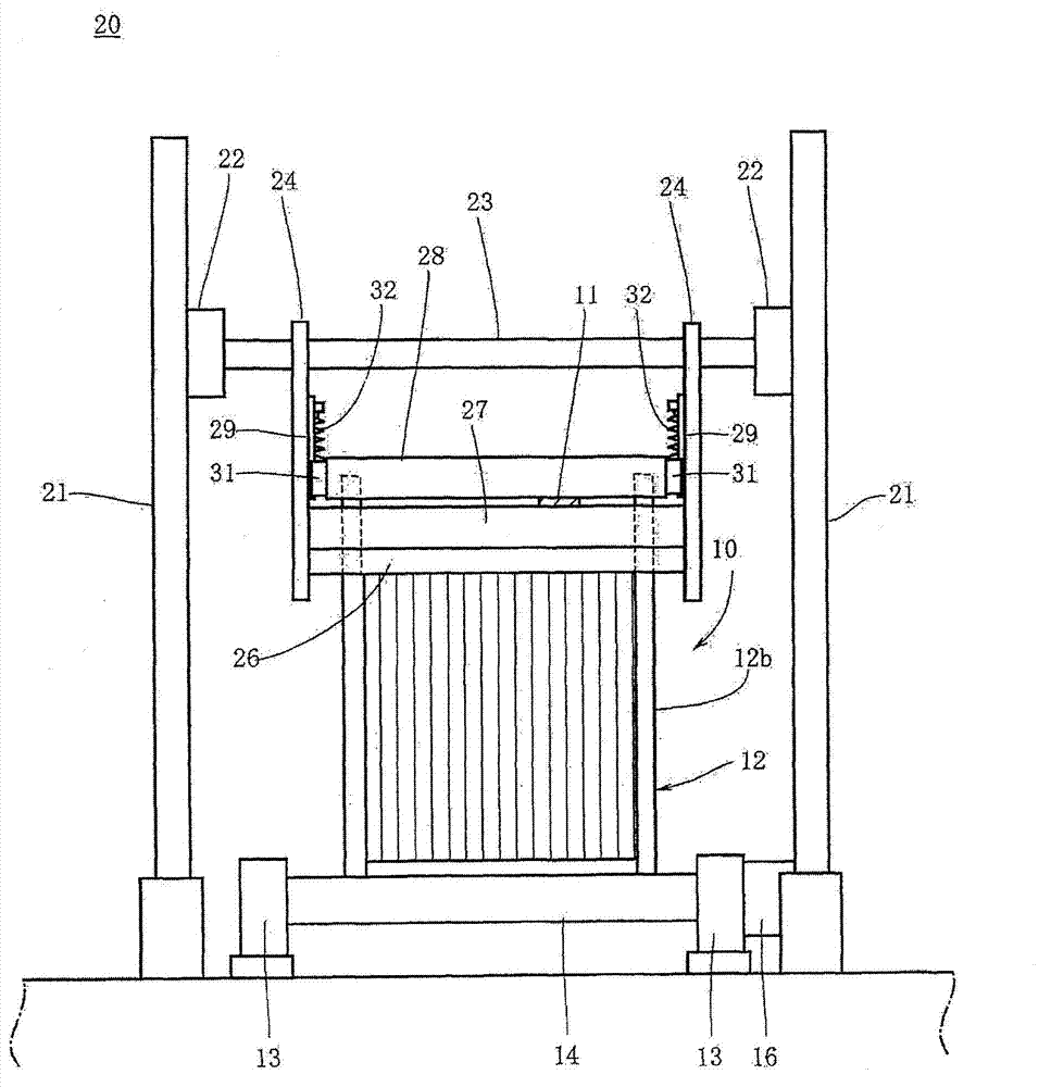
[0023] Figure 1~Figure 3 The device 20 for preventing wire slack of the present invention is shown in FIG. The wire slack prevention device 20 is provided together with the wire lead-out machine 10 that pulls the wire 11 out by rotating the bobbin 12 around which the wire 11 is wound. The wire 11 in this embodiment shows the case where a so-called flat wire whose cross-section is rectangular is used, but the wire 11 may be a so-called square wire whose cross-section is square, or may be a circular cross-section. The so-called circular line. In addition, the wire 11 may be, for example, a long strip like a film. The bobbin 12 for winding such a wire 11 has a cylindrical main body portion 12a ( figure 2 and Figure 4 ), the above-mentioned wire 11 is actually wound around the outer periphery of the main body portion 12a; the disc-shaped flange portion 12b is coaxially forme...


PUM


Abstract

The invention prevents a slack of a wire rod in a spool by preventing the wire rod fed by rotation of the spool from returning to the spool. A wire rod slack preventing device (20) is installed parallel to a wire rod feeding machine (10) feeding a wire rod (11) by rotating a spool (12), around which the wire rod (11) is wound, and has a reverse rotation roller (26) having a rotating axis which is parallel to a rotating axis of the spool and rotating in a reverse direction to a rotating direction of the spool while being in contact with the spool, a forward rotation roller (27) having a rotating axis which is parallel to the rotating axis of the reverse rotation roller (26) and rotating in the same direction as the spool while being in contact with the reverse rotation roller (26), and a pinching roller (28) having a rotating axis which is parallel to the rotating axis of the forward rotation roller (27) and pinching the wire rod, which is fed out of the spool, together with the forward rotation roller (27). Further, a wire rod slack preventing method draws the wire rod which is fed out due to the rotation of the spool, while pinching the wire rod by the forward rotation roller (27), which rotates with the rotation of the spool, together with the pinching roller (28).

Description

technical field [0001] The present invention relates to a device for preventing slack of a wire wound around a bobbin and a method for preventing slack of the wire wound around the bobbin provided together with a wire lead-out machine that pulls out the wire by rotating the bobbin on which the wire is wound. Background technique [0002] Conventionally, as a device for supplying a wire to a winding machine or the like, a wire lead-out machine that leads the wire out by rotating a bobbin on which the wire is wound is known. Figure 5 The wire export machine is shown in . Should Figure 5 The wire lead-out machine 1 shown has a rotating shaft 2 a horizontally, supports a bobbin 2 , and is provided with a motor 3 that rotates the bobbin 2 . By rotating the bobbin 2 with the motor 3, the wire 4 can be drawn out from the bobbin 2, and the wire 4 drawn out from the bobbin 2 is turned around by being wound around a pulley 5b pivotally supported by a swing lever 5a serving as a tens...

Claims


Application Information

Patent Timeline
Patent Type & Authority Applications(China)
IPC IPC(8): B65H59/04
CPCB65H49/24B65H51/10B65H51/20B65H51/30B65H54/10B65H2701/37H01F41/096B65H59/00B65H59/38
Inventor 高木智博
Owner NITTOKU ENG CO LTD
Learn More