Diesel engine with swirl chamber

A vortex chamber and diesel engine technology, which is applied to mechanical equipment, engine components, machines/engines, etc., can solve the problems of limited occupied volume, large gas flow loss, etc., and achieve favorable fluid dynamic characteristics, save occupied volume, and evenly distribute Effect

Inactive Publication Date: 2013-07-10
ROUSH AUTOMOBILE SYST SHANGHAI CO LTD
View PDF5 Cites 4 Cited by
  • Summary
  • Abstract
  • Description
  • Claims
  • Application Information

AI Technical Summary

Problems solved by technology

The gap between the piston and the cylinder head already occupies part of the effective minimum volume of the combustion chamber, so the volume that can be occupied by the dimple in the piston crown is limited
[0006] Chinese patent CN101131118A discloses a wide-mouth vortex chamber engine. The piston internal combustion engine adopts the vortex chamber and has many advantages, but its main disadvantage is that the loss of gas flow is large.

Method used


Image

  • Diesel engine with swirl chamber
  • Diesel engine with swirl chamber
  • Diesel engine with swirl chamber

Examples


Embodiment Construction

[0023] The present invention will be further described below in conjunction with the accompanying drawings and specific embodiments, but not as a limitation of the present invention.

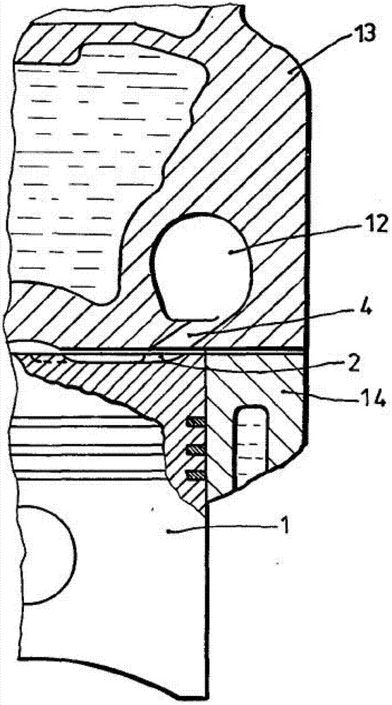
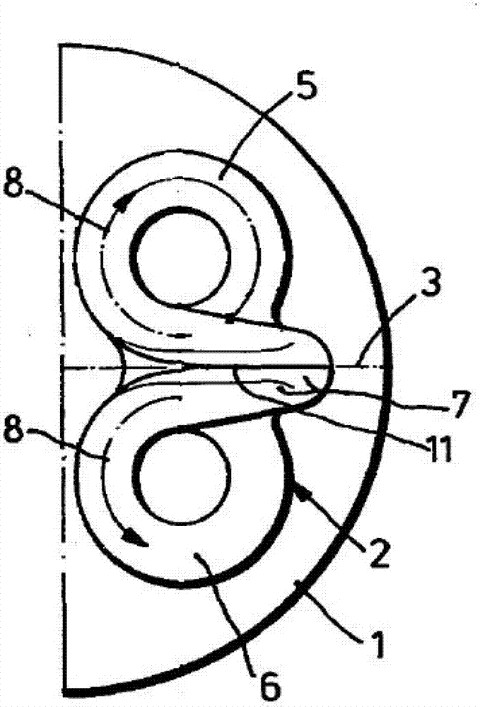
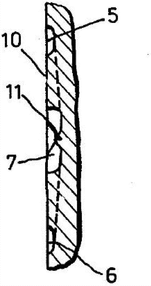
[0024] Such as figure 1 Shown is a sectional view of a diesel engine with a vortex chamber of the present invention, comprising a cylinder 14, a cylinder head 13 and a piston 1, the cylinder 14, the cylinder head 13 and the piston 1 enclosing a main combustion chamber, and the cylinder head 13 is provided with a passage 4 The vortex chamber 12 connected with the main combustion chamber, the piston top surface 10 is a wall surface of the main combustion chamber, and the piston top surface 10 is provided with a pit 2 arranged symmetrically with the passage 4, the pit 2 is an annular passage, and the pit 2 The radially overlapping portion is provided with an air intake drainage channel 7 adjacent to the opening of the channel 4 .

[0025] Further, during engine operation, fuel is injected into fi...


PUM


Abstract

The invention discloses a diesel engine with a swirl chamber. The diesel engine comprises a cylinder, a cylinder cover and a piston which define a main combustion chamber. The swirl chamber connected with the main combustion chamber is arranged in the cylinder cover through a passage, the top surface of the piston is a wall surface of the main combustion chamber, a pit which is symmetrical to the passage is arranged on the top surface of the piston, the pit is an annular passage, and an air inlet drainage passage close to an opening of the passage is arranged on the coincide position of the pit. The diesel engine has the advantages that the structural distribution of the pit is favorable for guiding combustion gas into the main combustion chamber so as to improve distribution of the combustion gas in the main combustion chamber.

Description

technical field [0001] The invention relates to a diesel engine, in particular to a diesel engine with a vortex chamber. Background technique [0002] Generally, a diesel engine has a swirl chamber, the swirl chamber is connected to the main combustion chamber through a channel. The top surface of the piston is provided with a pit adjacent to the opening of the passage into the main combustion chamber. In previous designs, the dimples are disk-shaped and symmetrically arranged on the top of the piston adjacent to the channel opening of the vortex chamber. The inlet flow channel is arranged between the disc-shaped pits for guiding the combustion gas from the channel into the pits. The dimples quickly and evenly distribute the combustion gases from the swirl chamber to the main combustion chamber, facilitating fast and even combustion. [0003] In a previous design case, the inlet channel had a tapered depth distribution, with a maximum depth adjacent to the channel opening...

Claims


Application Information

Patent Timeline
Patent Type & Authority Applications(China)
IPC IPC(8): F02F3/24
Inventor 陈新左朝凤李传友陈立新黄永刚
Owner ROUSH AUTOMOBILE SYST SHANGHAI CO LTD
Why Eureka
Try Eureka