
Depth image enhancement method based on anisotropic diffusion

A depth image and anisotropic technology, applied in image enhancement, image analysis, image data processing, etc., can solve the problems of inability to obtain accurate depth information, lack of depth information, and inability to fill depth missing areas, etc., to achieve a good filling effect , strong robustness and strong versatility

Active Publication Date: 2013-07-10
ZHEJIANG UNIV
View PDF7 Cites 18 Cited by
  • Summary
  • Abstract
  • Description
  • Claims
  • Application Information

AI Technical Summary

Problems solved by technology

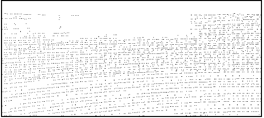
However, most of the depth images obtained by various existing devices have the problem of lack of depth information: the depth images obtained based on binocular stereo matching cannot obtain accurate depth information at long distances due to the limitation of the baseline length. Accurate depth information cannot be obtained in non-overlapping areas of the field of view of two cameras; depth images acquired by Microsoft’s Kinect are often affected by factors such as special material surfaces, ranging ranges, and object occlusions, and there are often partial depth missing areas; Data, the depth image obtained through coordinate conversion has accurate depth values, but the lidar scanning points are reflected in the depth image as discrete and sparse depth values, and there are a large number of depth missing areas on the depth image
However, this filter-based depth image enhancement is often very sensitive to the size of the depth-missing area. If the depth-missing area is large and the window size used for filtering is small, the depth-missing area cannot be filled.
However, if the window size is large, it will be difficult to preserve the detail information in the depth image.

Method used


Image

  • Depth image enhancement method based on anisotropic diffusion
  • Depth image enhancement method based on anisotropic diffusion
  • Depth image enhancement method based on anisotropic diffusion

Examples


specific Embodiment approach

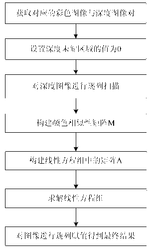
[0037] The depth image enhancement method proposed by the present invention based on theoretical derivation is guided by the color image corresponding to the depth image, and based on the known depth region of the depth image, completes the filling of the depth missing region of the depth image. The steps are as figure 2 As shown, the depth image during the implementation of the present invention is obtained by lidar, the color image is collected by the camera, and the algorithm of the present invention is realized by Matlab. The specific implementation is as follows:

[0038] Step 1) Use the camera to take a color image, and use the depth acquisition device to obtain the depth information of the same scene, and then map the depth information to the color image coordinate system to obtain the depth image, and perform the pixel points with the same row and column position in the two images one by one correspond;

[0039] The depth information obtained by the lidar can use the rota...


PUM


Abstract

The invention discloses a depth image enhancement method based on anisotropic diffusion. The similarity among pixel points of a color image corresponding to a depth image is used as a basis of depth diffusion, and based on the known depth of the depth image, filling of a depth missing region of the depth image is finished. Through the depth image enhancement method based on the anisotropic diffusion, the defect that in a traditional depth enhancement method based on interpolation, edges of an object are blurry is overcome, meanwhile, the limit of the size of a wave filtering window in a depth enhancement method based on wave filtering is broken through, and the depth image enhancement method based on the anisotropic diffusion has the advantages of being high in universality, high in robustness and the like. The depth image enhancement method based on the anisotropic diffusion can be widely used for a variety of depth images which have missing depth regions, and in a practical application process, based on the color image and the depth image which are in correspondence to each other, a good depth image missing region filling effect can be achieved.

Description

Technical field [0001] The invention relates to a depth image enhancement method, in particular to an enhancement method for filling missing regions of a depth image based on anisotropic diffusion. Background technique [0002] The depth image is used to express the distance between points in the scene relative to the camera. Depth image has a wide range of applications in various applications of computer vision, which provides more possibilities for methods such as tracking, classification, and recognition in computer vision. [0003] The acquisition of depth images includes active acquisition and passive acquisition. Among them, the binocular stereo vision method is commonly used in passive acquisition, which uses two cameras separated by a certain distance to acquire scene images at the same time, and uses the geometric relationship between the two cameras to finally generate depth images; while active acquisition includes lidar, Structured light and other methods are characte...

Claims


Application Information

Patent Timeline
IPC IPC(8): G06T7/00G06T5/00
Inventor 刘俊毅龚小谨刘济林
Owner ZHEJIANG UNIV
Learn More