Connecting structure of wallboard and floor, ground ring beam and modular integrated house

A technology for integrating houses and ground ring beams, applied in building structures, buildings, etc., can solve problems such as immovable components, damage to wall panels, and fixed connection of wall panels

Active Publication Date: 2013-07-17
HENAN TIANFON ENERGY SAVING PANEL SCI & TECH
View PDF4 Cites 12 Cited by
  • Summary
  • Abstract
  • Description
  • Claims
  • Application Information

AI Technical Summary

Problems solved by technology

In the construction sites of major central cities and southern coastal cities, the amount of disassembled integrated houses is increasing year by year, but the existing prefabricated integrated houses on the market are all one-off buildings, which basically cannot be moved or moved after assembly. Most of the components are damaged during repeated disassembly and assembly, and cannot be reused many times
This fast-installed integrated house that cannot be reused many times is similar to a modular fast-assembled house disclosed in the Chinese invention patent with the publication number CN 102635248.A. The fixed connection has inserts, and the inserts are fixedly connected to the cast-in-place concrete floor through fastening rivets. Therefore, when the house is demolished, the connecting screws need to be selected first. In the process of selecting the connecting screws, the Damage to the wall panels is inevitable, so that the wall panels cannot be fixedly connected with the appropriate inserts again, and since the concrete floor is cast-in-place before assembling the fast-installed integrated house, it needs to be re-used when it needs to be reused many times. Pouring the concrete floor, resulting in waste of the original concrete floor when it is reused many times

Method used


Image

  • Connecting structure of wallboard and floor, ground ring beam and modular integrated house
  • Connecting structure of wallboard and floor, ground ring beam and modular integrated house
  • Connecting structure of wallboard and floor, ground ring beam and modular integrated house

Examples


Embodiment Construction

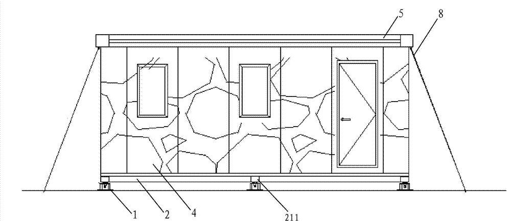
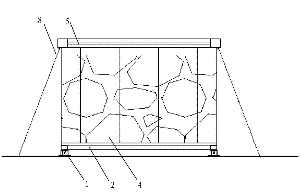
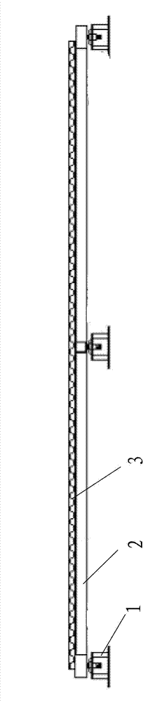
[0045] The embodiment of the modular integrated house of the present invention: as Figure 1 to Figure 15 As shown, the modular integrated house includes an adjustment bracket 1 , a ground ring beam 2 , a floor 3 , a wall panel 4 , a top ring beam 5 and a roof panel 6 arranged sequentially from bottom to top. Such as Figure 3 to Figure 11 As shown, the geosphere beam 2 connects the wallboard 4 and the floor 3 together to form a connection structure between the wall and the floor. The geosphere beam 2 is a square frame-shaped ring beam surrounded by four ground beam profiles 21, each The ground beam profiles 21 are all square steel pipes. On the top surface of the ground beam profiles 21, the ground channel beams 22 distributed close to the outer edge are fixed by rivets. The ground channel beams 22 are square channel steel with the opening facing upwards, and are used to The rivets fixed on the top surface of the geospheric beam 2 by the geospheric beam 22 are alternately ar...


PUM


Abstract

The invention discloses a connecting structure of a wallboard and a floor, a ground ring beam and a modular integrated house. According to the modular integrated house disclosed by the invention, the floor is overlapped on a supporting surface on the inner side of the top surface of the square-frame-shaped ground ring beam, and a wallboard connecting groove, into which the bottom of the wallboard is inserted, is formed in the outer side of the ground ring beam. When being used, the modular integrated house can be conveniently and rapidly assembled together by the structure, and the wallboard surrounds the floor and is used for limiting the floor; while the modular integrated house needs to be disassembled, the wallboard can be directly pulled out from the wallboard mounting groove to remove the connection between the wallboard and the ground ring beam and eliminate the limiting action of the wallboard to the floor, so that each component part of the modular integrated house can be reused for many times in the disassembling process of the modular integrated house, and the effect that the whole modular integrated house can be recycled for many times is achieved.

Description

technical field [0001] The invention relates to the technical field of fast-installed integrated houses, and also relates to a connection structure between a wall panel and a floor of a quickly-installed integrated house. Background technique [0002] At present, the construction industry is an important industry closely related to people's daily life, and its architectural forms show a trend of diversification with the development of the times and technology. With the development of science and technology and the intensification of problems such as lack of land resources and difficult disposal of construction waste, the reusable and rapidly assembled integrated building system, as a kind of architectural diversification, has become an important research topic in the field of architecture. Reusable fast-assembled buildings pay more attention to the relationship between the system, components and materials, which is an important way and method of innovation in the constructio...

Claims


Application Information

Patent Timeline
Patent Type & Authority Applications(China)
IPC IPC(8): E04B1/61E04B1/343
Inventor 杨建峰严亚刚匡合李晨张艳波闫凯歌
Owner HENAN TIANFON ENERGY SAVING PANEL SCI & TECH
Why Eureka
Try Eureka