Holder, holder with flat conductor and assembly of holder with electrical connector

A flat conductor and electrical connector technology, applied in the parts, connections, circuits and other directions of the connection device, can solve problems such as difficulties, achieve a good connection state, and prevent damage.

Inactive Publication Date: 2013-07-17
HIROSE ELECTRIC GROUP
View PDF6 Cites 4 Cited by
  • Summary
  • Abstract
  • Description
  • Claims
  • Application Information

AI Technical Summary

Problems solved by technology

However, it is very difficult to manufacture a flat conductor with a reinforcement plate by the above-mentioned process beca

Method used


Image

  • Holder, holder with flat conductor and assembly of holder with electrical connector
  • Holder, holder with flat conductor and assembly of holder with electrical connector
  • Holder, holder with flat conductor and assembly of holder with electrical connector

Examples


no. 1 approach

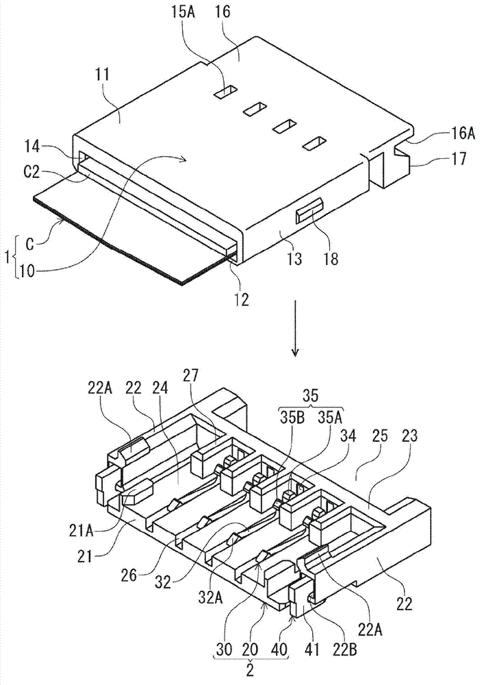
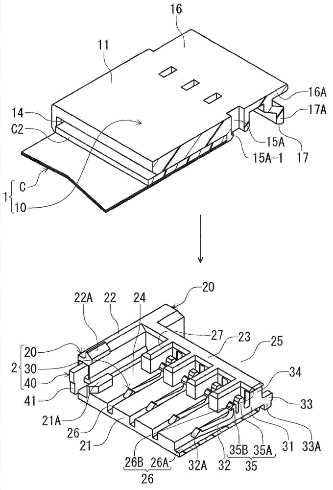
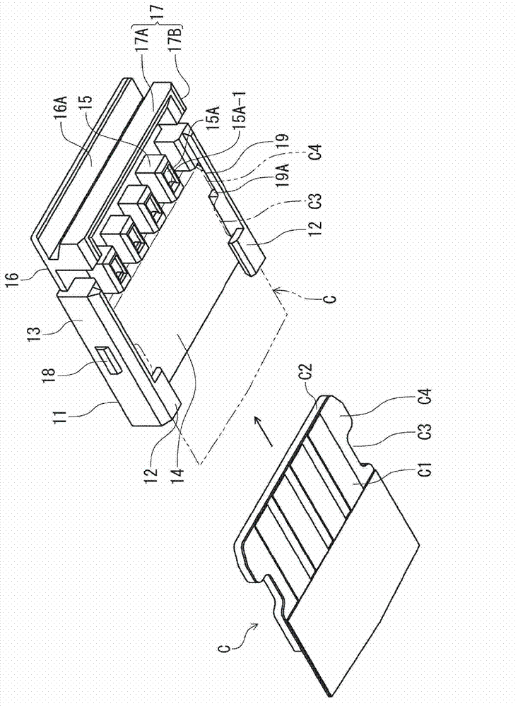
[0054] figure 1 It is a perspective view showing the flat conductor-attached holder and the electric connector of this embodiment, and shows the state before connection. figure 2 yes figure 1 A perspective sectional view of a flat conductor holder and an electrical connector of , showing a section at the position of the terminal in the width direction of the flat conductor. image 3 yes figure 1 The perspective view before assembly of the holder with the flat conductor is shown from the lower side, showing the state before assembly when the front end portion of the flat conductor is separated from the holder. Additionally, in the image 3 In , the outline of the front end portion of the flat conductor when it is attached to the holder is indicated by a two-dot chain line.

[0055] Such as figure 1 As shown, the holder 1 with a flat conductor of this embodiment is assembled by attaching the front end portion of the flat conductor C to the holder 10 . In this holder 1 wit...

no. 2 approach

[0091] In the first embodiment, the terminal 30 of the connector 2 does not have a part to engage with the flat conductor C, but Figure 6 The present embodiment shown is different from the first embodiment in that the terminal has a protrusion 76 engaged with the flat conductor C at the rear.

[0092] Below, according to Figure 6 This embodiment will be described. Figure 6 It is a perspective cross-sectional view of the flat conductor-attached holder 3 and the connector 4 of the present embodiment, showing a cross-section at the position of the terminal 70 in the width direction of the flat conductor C. The structure of the flat conductor C of this embodiment is the same as that of 1st Embodiment except the hole part C5 mentioned later is formed. exist Figure 6 In , with respect to the flat conductor C, the same symbols are attached to the parts corresponding to those of the first embodiment. In addition, the structure of the holder of this embodiment is the same as th...


PUM


Abstract

The invention provides a holder, a holder with a flat conductor and an assembly of holder with electrical connector. According to the invention, when the flat conductor is connected to the electrical connector from the top, circuit unit damage of the flat conductor can be reliably prevented without thickening a reinforcing plate or arranging the reinforcing plate, and thus a good connection state of the flat conductor and the electrical connector can be realized. The holder (10) comprises an upper supporting part (11) capable of supporting an upper surface of a front-end part of the flat conductor, a lower supporting part (12) capable of supporting a part of a lower surface of the front-end part of the flat conductor, and a connecting part (13) capable of connecting the upper supporting part (11) and the lower supporting part (12) at a corresponding edge position of the front-end part. The holder (10) is connected to the electrical connector (2) from the top in such a way that a circuit part exposed at an area of the lower surface of the front-end part of the flat conductor (C) corresponding to the lower supporting part (12) is contacted with a terminal of the electrical connector (2).

Description

technical field [0001] The invention relates to a holder mounted on a flat conductor, a holder with a flat conductor on which a flat conductor is installed, an assembly of the holder with a flat conductor and an electrical connector. Background technique [0002] As a connection form of a flat conductor and an electrical connector, the connection form of patent document 1 is known, for example. Patent Document 1 discloses a form in which a front end portion of a flat conductor extending in the front-rear direction is connected to an electrical connector from above. The lower surface of the front end portion of the flat conductor exposes the circuit portion, and the upper surface thereof has a reinforcing plate attached thereto. In addition, ear portions as engaging protrusions are formed on both side end edges of the reinforcing plate at positions corresponding to both side edges in the width direction of the flat conductor, and the ear portions protrude outward in the widt...

Claims


Application Information

Patent Timeline
IPC IPC(8): H01R13/639H01R12/77
Inventor 大塚悠华玉木祥一郎
Owner HIROSE ELECTRIC GROUP
Why Eureka
Try Eureka