
Reverse connection prevention circuit for direct current power supply

A technology of anti-reverse connection circuit and DC power supply, applied in the direction of emergency protection circuit devices, electrical components, etc., can solve the problems of increasing system power consumption and instability factors, low system efficiency and reliability, and large loss of diode D1, etc. Achieve the effect of increasing system power consumption and instability factors

Active Publication Date: 2013-07-17
DALIAN SHINERGY SCI & TECH DEV
View PDF6 Cites 8 Cited by
  • Summary
  • Abstract
  • Description
  • Claims
  • Application Information

AI Technical Summary

Problems solved by technology

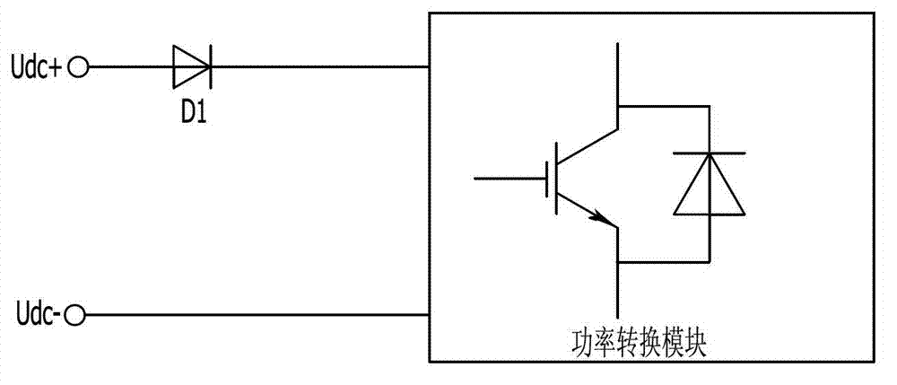
[0002] The input ends of traditional photovoltaic inverters and energy storage inverters are connected to DC power. In order to improve system safety and reliability, it is often necessary to add a DC power anti-reverse connection structure at the output of the DC power. Refer to figure 1 Shown is the anti-reverse connection circuit of the DC power supply in the prior art, which adopts the series connection of diodes in the output end circuit of the DC power supply to prevent the electronic components from being damaged due to the reverse connection of the positive and negative poles of the DC power supply. In the figure, Udc+, Udc- They are the positive and negative input terminals of the DC power supply, and D1 is a diode. The power conversion module is the core structure of the photovoltaic inverter and energy storage inverter as the load of the DC power supply. This method is costly and the loss on the diode D1 is relatively large. Large, high heat dissipation, increase system power consumption and instability factors, low system efficiency and reliability, and for a DC system with bidirectional flow of electric energy, such as a DC power supply connected to a photovoltaic inverter or energy storage inverter circuit, then The use of this anti-reverse diode method cannot solve the problem of reverse polarity of the DC power supply. At the same time, in the case of high-current applications, it is difficult to find a single diode module with a capacity and parameters that meet the system current requirements. It is the current anti-reverse protection Therefore, a brand-new DC power supply anti-reverse connection measure is imminent, especially for solving the problem of anti-reverse connection of DC power supply with bidirectional flow of energy

Method used


Image

  • Reverse connection prevention circuit for direct current power supply
  • Reverse connection prevention circuit for direct current power supply

Examples


Embodiment Construction

[0017] In order to make the object, technical solution and advantages of the present invention clearer, the present invention will be further described in detail below in conjunction with the accompanying drawings and embodiments. It should be understood that the specific embodiments described here are only used to explain the present invention, not to limit the present invention.

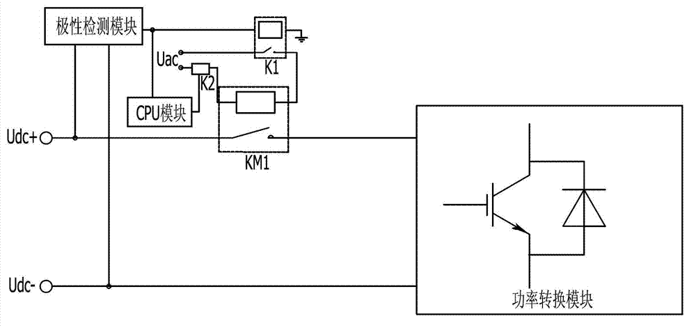
[0018] Such as figure 2 The DC power supply anti-reverse connection circuit shown includes: a polarity detection module connected between the positive and negative input terminals Udc+ and Udc- of the DC power supply for detecting the positive or reverse connection of the DC power supply and outputting corresponding signals; a relay K1; one end of the coil of the relay K1 is connected to the output end of the polarity detection module, and the contact of the relay K1 is connected in series with the coil of the contactor KM1; the contactor KM1; the main contact of the contactor KM1 is connected in ...


PUM


Abstract

The invention discloses a reverse connection prevention circuit for a direct current power supply. The circuit comprises a polarity detection module, a relay and a contactor, wherein the polarity detection module is connected between the positive and negative input ends of the direct current power supply, and is used for detecting the normal connection or reverse connection of the direct current power supply, and outputting a corresponding signal; one end of a coil of the relay is connected with the output end of the polarity detection module, and a contact of the relay is connected in series with a coil of the contactor; and a main contact of the contactor is connected in series between the positive input end of the direct current power supply and a load. The circuit is safe, reliable and particularly effective to a high-power direct current system, and can be directly applied to an energy bidirectional flowing direct current power system to solve the problem of reverse polarity connection of the system, and the loss of system efficiency is avoided.

Description

technical field [0001] The invention relates to a DC power supply anti-reverse connection circuit. Background technique [0002] The input ends of traditional photovoltaic inverters and energy storage inverters are connected to DC power. In order to improve system safety and reliability, it is often necessary to add a DC power anti-reverse connection structure at the output of the DC power. Refer to figure 1 Shown is the anti-reverse connection circuit of the DC power supply in the prior art, which adopts the series connection of diodes in the output end circuit of the DC power supply to prevent the electronic components from being damaged due to the reverse connection of the positive and negative poles of the DC power supply. In the figure, Udc+, Udc- They are the positive and negative input terminals of the DC power supply, and D1 is a diode. The power conversion module is the core structure of the photovoltaic inverter and energy storage inverter as the load of the DC pow...

Claims


Application Information

Patent Timeline
IPC IPC(8): H02H11/00
Inventor 蒲延洲许明夏
Owner DALIAN SHINERGY SCI & TECH DEV
Learn More