Limiting device
A technology of a limit device and a limit block, which is applied to roads, road repairs, roads, etc., can solve the problems of a limit device with complex structure, high manufacturing cost, and inconvenient operation, and achieve compact structure, low manufacturing cost, and easy processing and installation. convenient effect
- Summary
- Abstract
- Description
- Claims
- Application Information
AI Technical Summary
Problems solved by technology
Method used
Image

Examples
Embodiment Construction
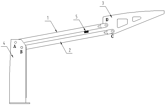
[0012] Below in conjunction with accompanying drawing and embodiment the present invention is further described:
[0013] figure 1 The invention comprises a column 1 and a column 2, a ceiling 3 and a mounting base 4, one end of the column 1 is hinged to the mounting base 4 at point A; the other end of the column 1 is hinged to the ceiling 3 at point D; one end of the column 2 is connected to the installation The seat 4 is hinged at point B; the other end of the column 2 and the ceiling 3 are hinged at point C; a limiting block 5 is arranged between the column 1 and the column 2, and one end of the limiting block 5 is welded on the column 1. In other embodiments, One end of the limit block 5 can also be welded on the column 2 as an option.
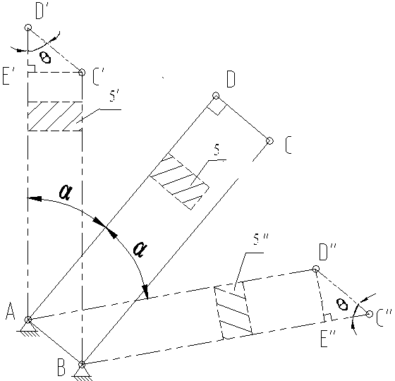
[0014] The connection AB between the hinge point A of the mounting base 4 and the column 1 and the hinge point B between the mounting base 4 and the column 2, the axis AD of the column 1, the axis BC of the column 2, and the hinge point D ...
PUM
 Abstract
Description
Claims
Application Information