
Air door opening and closing device

A switching device and damper technology, applied in door/window fittings, mine/tunnel ventilation, wing fan components, etc., can solve the problem that two doors cannot be locked with each other reliably and effectively, and the underground damper cannot be opened and closed quickly and easily. problems, to avoid the accident of the damper, improve the stability and reliability, and ensure the effect of mutual locking

Active Publication Date: 2013-07-24
HUAINAN MINING IND GRP
View PDF5 Cites 14 Cited by
  • Summary
  • Abstract
  • Description
  • Claims
  • Application Information

AI Technical Summary

Problems solved by technology

[0006] The invention provides a damper switch device, which solves the technical problems in the prior art that the downhole damper cannot be opened and closed quickly and conveniently, and the two leaves of the damper cannot be reliably and effectively locked to each other

Method used


Image

  • Air door opening and closing device
  • Air door opening and closing device
  • Air door opening and closing device

Examples


Embodiment 1

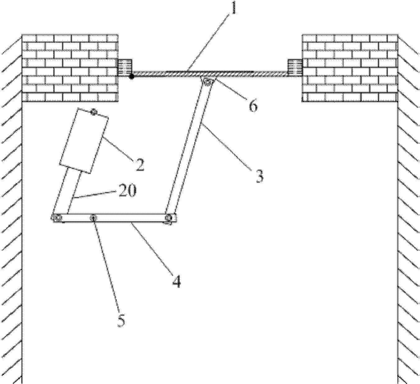
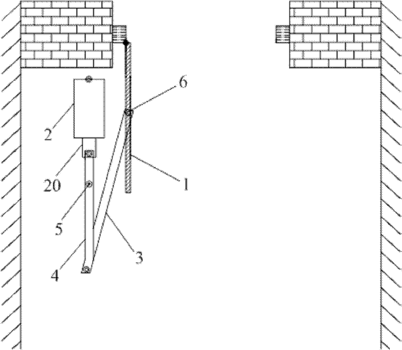
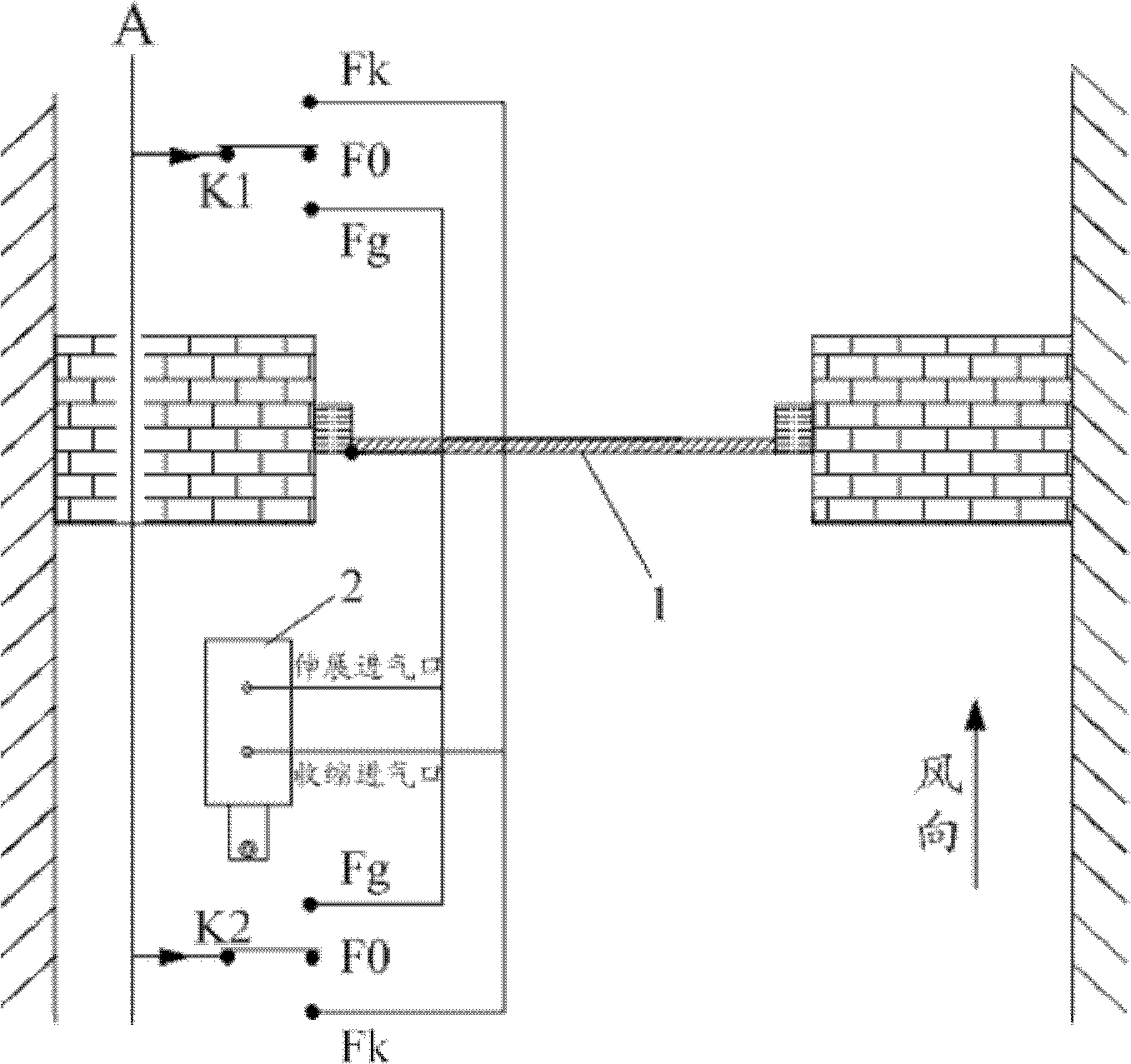
[0027] See Figure 1 to Figure 3 . figure 1 It is a structural schematic diagram of the air door switch device in the closed state according to Embodiment 1 of the present invention. figure 2 It is a structural schematic diagram of the damper switch device in the first embodiment of the present invention when it is in an open state. image 3 It is a schematic diagram of the installation layout and air path control of the damper switch device according to Embodiment 1 of the present invention.

[0028] Such as Figure 1 to Figure 3 As shown, a damper switch device provided in Embodiment 1 of the present invention includes: a first connecting rod 3, a second connecting rod 4, a cylinder 2 and an air circuit control unit, wherein one end of the first connecting rod 3 is connected to the The door leaf 1 in the underground roadway is hinged, the other end of the first connecting rod 3 is hinged with one end of the second connecting rod 4; the other end of the second connecting ...

Embodiment 2

[0036] See Figure 4 to Figure 6 . Figure 4 It is a structural schematic diagram of the damper switch device according to the second embodiment of the present invention. Figure 5 It is a connection diagram of part of the air circuit control of the damper switch device according to the second embodiment of the present invention. Figure 6 It is a schematic diagram of the installation layout and air circuit control of the damper switch device according to the second embodiment of the present invention.

[0037] Such as Figure 4 to Figure 6 As shown, a damper switch device provided by Embodiment 2 of the present invention includes: a first connecting rod 3, a second connecting rod 4, a third connecting rod 7, a fourth connecting rod 8, a first cylinder 200, a second cylinder 400. The first air circuit control unit and the second air circuit control unit, wherein one end of the first connecting rod 3 is hinged to the first door leaf 100 arranged in the underground roadway, a...


PUM


Abstract

The invention discloses an air door opening and closing device, which comprises a first connecting rod, a second connecting rod, an air cylinder and an air channel control unit, wherein one end of the first connecting rod is hinged to a door leaf arranged in a mine tunnel, and the other end of the first connecting rod is hinged to one end of the second connecting rod; and the other end of the second connecting rod is hinged to a telescopic link of the air cylinder, a stationary shaft is arranged on the second connecting rod, and when the telescopic link of the air cylinder stretches or contracts under the control of the air channel control unit, the second connecting rod rotates around the stationary shaft under the driving of the telescopic link of the air cylinder and drives the first connecting rod to move so as to open or close the door leaf. With the air door opening and closing device, automatic opening and closing of the door leaf of an air door can be realized, so that the technical problem that the air door cannot be quickly and conveniently opened and closed in the prior art is solved.

Description

technical field [0001] The invention relates to mine ventilation technology, in particular to a damper switch device. Background technique [0002] In coal mining, the safety of coal mines is very important. Among them, the mine ventilation system is the key to ensure the safety of the mine, and the damper in the mine ventilation system is the key to maintaining the stable operation of the mine ventilation system. The damper is mainly set up for the passage of personnel and materials underground. While ensuring the passage of personnel and materials underground, it is also used to adjust the underground air flow to avoid short-circuit of air flow and ensure the reliable operation of the entire ventilation system. Whether the damper can be opened and closed quickly and conveniently will directly affect the production safety of the mine. [0003] At present, the opening and closing methods of the damper are mainly opened or closed by manual pulling, pushing, etc., because the...

Claims


Application Information

Patent Timeline
Patent Type & Authority Applications(China)
IPC IPC(8): E21F1/12E05F15/04E05F15/53
Inventor 蒋光勇沈强何强革张家胜余淮史文东
Owner HUAINAN MINING IND GRP
Learn More